PDF Publication Title:
Text from PDF Page: 006
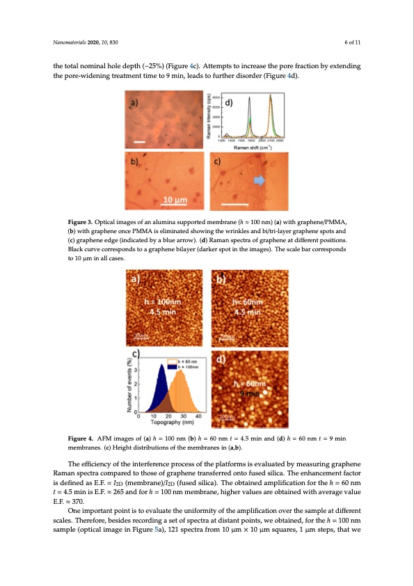
Nanomaterials 2020, 10, 830 6 of 11 the total nominal hole depth (~25%) (Figure 4c). Attempts to increase the pore fraction by extending tNhaenopmoarter-iawlsi2d0e2n0,i1n0g, xtrFeOaRtmPEeEnRt RtiEmVIeEtWo 9 min, leads to further disorder (Figure 4d). 6 of 11 Figure 3. Optical images of an alumina supported membrane (h ≈ 100 nm) (a) with graphene/PMMA, (b) with graphene once PMMA is eliminated showing the wrinkles and bi/tri-layer graphene spots and (c) graphene edge (indicated by a blue arrow). (d) Raman spectra of graphene at different positions. Black curve corresponds to a graphene bilayer (darker spot in the images). The scale bar corresponds to 10 μm in all cases. Membranes with h = 60 nm were fabricated to optimize the E.F., however, for such small pore depth the quality of the membranes is compromised in terms of the order of the pores as well as in the height uniformity. The AFM topographic images show an increased disorder of the pores for the Figure 3. Optical images of an alumina supported membrane (h ≈ 100 nm) (a) with graphene/PMMA, h = 6F0ignumrem3.eOmpbtircanl eimcaogmespoafraendatloumthineahsu=p1p0o0rtnedmmoenmeb(rFanigeu(hre≈41a0,0b)n,ma)ls(oa), wthiethhgeriagphtendei/sPtrMibMuAti,on of (b) with graphene once PMMA is eliminated showing the wrinkles and bi/tri-layer graphene spots (b) with graphene once PMMA is eliminated showing the wrinkles and bi/tri-layer graphene spots and the AFM image in the case of the 60 nm sample is increased significantly, especially in comparison (acn)dgr(acp)hgernaephedenge (einddgeica(itnedibcayteadblbuye arrbolwue).a(rdr)oRwa)m. (adn) sRpaemctaranosfpgercatpraheonfegartadphiffeenrenattpdoisfifteiroenst. with the total nominal hole depth (~25%) (Figure 4c). Attempts to increase the pore fraction by Bploasciktiocunsrv.eBlcaocrkrecsuprovnedcsotroreaspgroanpdhsetnoeabiglaryaperh(ednaerkbeilrayspeort(dinarthkerimspaogteisn).tThheeimscaglesb)a.rTchoerrsecsapleonbdasr extending the pore-widening treatment time to 9 min, leads to further disorder (Figure 4d). tcor1r0esμpmonindsaltloc1a0seμsm. in all cases. Membranes with h = 60 nm were fabricated to optimize the E.F., however, for such small pore depth the quality of the membranes is compromised in terms of the order of the pores as well as in the height uniformity. The AFM topographic images show an increased disorder of the pores for the h = 60 nm membrane compared to the h = 100 nm one (Figure 4a,b), also, the height distribution of the AFM image in the case of the 60 nm sample is increased significantly, especially in comparison with the total nominal hole depth (~25%) (Figure 4c). Attempts to increase the pore fraction by extending the pore-widening treatment time to 9 min, leads to further disorder (Figure 4d). Figure4. AFMimagesof(a)h=100nm(b)h=60nmt=4.5minand(d)h=60nmt=9min Figure4.AFMimagesof(a)h=100nm(b)h=60nmt=4.5minand(d)h=60nmt=9minmembranes. membranes. (c) Height distributions of the membranes in (a,b). (c) Height distributions of the membranes in (a) and (b). The efficiency of the interference process of the platforms is evaluated by measuring graphene The efficiency of the interference process of the platforms is evaluated by measuring graphene Raman spectra compared to those of graphene transferred onto fused silica. The enhancement factor Raman spectra compared to those of graphene transferred onto fused silica. The enhancement factor is defined as E.F. = I2D (membrane)/I2D (fused silica). The obtained amplification for the h = 60 nm is defined as E.F. = I2D (membrane)/I2D (fused silica). The obtained amplification for the h = 60 nm t = t = 4.5 min is E.F. ≈ 265 and for h = 100 nm membrane, higher values are obtained with average value E.F. ≈ 370. One important point is to evaluate the uniformity of the amplification over the sample at different scales. Therefore, besides recording a set of spectra at distant points, we obtained, for the h = 100 nm Figure4.AFMimagesof(a)h=100nm(b)h=60nmt=4.5minand(d)h=60nmt=9minmembranes. sample (optical image in Figure 5a), 121 spectra from 10 μm × 10 μm squares, 1 μm steps, that we (c) Height distributions of the membranes in (a) and (b). The efficiency of the interference process of the platforms is evaluated by measuring graphene Raman spectra compared to those of graphene transferred onto fused silica. The enhancement factor is defined as E.F. = I2D (membrane)/I2D (fused silica). The obtained amplification for the h = 60 nm t =PDF Image | Supported Ultra-Thin Alumina Membranes with Graphene
PDF Search Title:
Supported Ultra-Thin Alumina Membranes with GrapheneOriginal File Name Searched:
nanomaterials-10-00830-v2.pdfDIY PDF Search: Google It | Yahoo | Bing
Turbine and System Plans CAD CAM: Special for this month, any plans are $10,000 for complete Cad/Cam blueprints. License is for one build. Try before you buy a production license. More Info
Waste Heat Power Technology: Organic Rankine Cycle uses waste heat to make electricity, shaft horsepower and cooling. More Info
All Turbine and System Products: Infinity Turbine ORD systems, turbine generator sets, build plans and more to use your waste heat from 30C to 100C. More Info
CO2 Phase Change Demonstrator: CO2 goes supercritical at 30 C. This is a experimental platform which you can use to demonstrate phase change with low heat. Includes integration area for small CO2 turbine, static generator, and more. This can also be used for a GTL Gas to Liquids experimental platform. More Info
Introducing the Infinity Turbine Products Infinity Turbine develops and builds systems for making power from waste heat. It also is working on innovative strategies for storing, making, and deploying energy. More Info
Need Strategy? Use our Consulting and analyst services Infinity Turbine LLC is pleased to announce its consulting and analyst services. We have worked in the renewable energy industry as a researcher, developing sales and markets, along with may inventions and innovations. More Info
Made in USA with Global Energy Millennial Web Engine These pages were made with the Global Energy Web PDF Engine using Filemaker (Claris) software.
Infinity Turbine Developing Spinning Disc Reactor SDR or Spinning Disc Reactors reduce processing time for liquid production of Silver Nanoparticles.
| CONTACT TEL: 608-238-6001 Email: greg@infinityturbine.com | RSS | AMP |