PDF Publication Title:
Text from PDF Page: 007
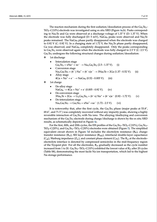
Materials 2022, 15, x FOR PEER REVIEW 8 of 15 Materials 2022, 15, 6231 Materials 2022, 15, x FOR PEER REVIENWa2Te peaks remained. The NaGa4 phase partly disappeared when the electrod8e owf a1s5 the electrode was fully discharged (D: 5 mV), NaGa4 peaks were observed and Na2Te The reaction mechanism during the first sodiation/desodiation process of the Ga2Te3– TiO2–C(10%) electrode was investigated using ex situ XRD (Figure 4a,b). Peaks The reaction mechanism during the first sodiation/desodiation process of the Ga2Te3– corresponding to Na2Te and Ga were observed at a discharge voltage of 1.37 V (D: 1.37 TiO2–C(10%) electrode was investigated using ex situ XRD (Figure 4a,b). Peaks correspond- V). When the electrode was fully discharged (D: 5 mV), NaGa4 peaks were observed and ing to Na2Te and Ga were observed at a discharge voltage of 1.37 V (D: 1.37 V). When charged to 0.92 V (C: 0.92V). In a charging state of 1.72 V, the Na2Te phase partly peaks remained. The NaGa4 phase partly disappeared when the electrode was charged 7 of 15 disappeared, Ga was observed, and NaGa4 completely disappeared. Only the peaks to 0.92 V (C: 0.92 V). In a charging state of 1.72 V, the Na2Te phase partly disappeared, cGoarrwesapsoonbdsinergvteodG, an2Tde3NwaeGrea obcosemrvpeledtealgyaidniswaphpeneatrhede.leOctnrloydtehwe apsefauklslyccohrarergspedontodi2n.g5 4 The reaction mechanism during the first sodiation/desodiation process of the Ga2Te3– VtoG(aC:Te2.w5ereVo).bseGrav2eTde3agauindwerhgeonetshetehlectrfodlleowiansgfulslytruchctaurrgaeldtcoh2a.n5gVes(C:d2u.5rinVg). 23 TiO2–C(10%) electrode was investigated using ex situ XRD (Figure 4a,b). Peaks sGoadiTaetiounn/desrogdoieastitohne:following structural changes during sodiation/desodiation: 23 corresponding to Na2Te and Ga were observed at a discharge voltage of 1.37 V (D: 1.37 V). W1hsstetndiitshcehaearlregcetrode was fully discharged (D: 5 mV), NaGa4 peaks were observed and Na2Te peaks remained. The NaGa4 phase partly disappeared when the electrode was • Intercalation stage • Intercalation stage +− charged to 0.92 V (C: 0.92V). In a charging state of 1.72 V, the Na2Te phase partly Ga2Te3 + xNa + xe → NaxGa2Te3 (2.5−1.37 V). (i) Ga2Te3 + xNa+ + xe− → NaxGa2Te3 (2.5−1.37 V). (i) disappeared, Ga was observed, and NaGa4 completely disappeared. Only the peaks • Conversion stage −+−− correspondNiangGtao GTea2T+e3(6we)rNe oabs+er(v6edx)aegai→n w3NheanTthee+e2leGcatr(o1d.3e7w−a0s.5f2ulVly).cha(rigi)ed to 2.5 • C o n vx e r s 2i o n 3 s t a g e 2 V (C•: 2A.5lloyV)s.tagGe a2Te3 undergoes the following structural changes during NaxGa2Te3 + (6−) Na+ + (6−x)e− → 3Na2Te + 2Ga (1.37−0.52 V). (ii) +− sodiation/d4Gesao+diNataion+: e → NaGa4 (0.52−0.005 V). (iii) • Alloy stage 1ssttdcihsacrhgaerge +− 4•Ga +DNea-al+loey s→tagNe aGa4 (0.52−0.005 V). (iii) • Intercalation stage + - NaGa → 4Ga + Na + e (0.005−0.92 V). (iv) 1st charge 4 Ga2Te3 + xNa+ + xe− → NaxGa2Te3 (2.5−1.37 V). (i) • De-conversion stage • De-alloy stage − + 3Na Te+2Ga→Li Ga Te +(6 x)Na +(6 x)e (0.92−1.72V). • Conv2ersion stage x 2 3 • De-intercalation+ sta-ge − − (v) NaGa4 → 4Ga + Na + e (0.005−0.92 V). (iv) NaxGa2Te3 + (6−) Na+ + (6−x)e− → 3Na2Te + 2Ga (1.37−0.52 V). (ii) NaxGa2Te3 → Ga2Te3 + xNa+ +xe− (1.72−2.5 V). (vi) • De-conversion stage • Alloy stage ◦ It is noteworthy that, after the first cycle, the Ga Te phase (major peaks at 53.8 , −+−−23 3Na2Te + 2Ga → LixGa2Te3 + (6 x) Na + (6 x)e (0.92−1.72 V). (v) +− ◦4Ga + Na ◦+ e → NaGa4 (0.52−0.005 V). (iii) 69.4 , and 71.5 ) was completely recovered without any impurity peaks, showing a highly • De-intercalation stage rever1ssitbclehainrgteraction of Ga2Te3 with Na ions. The alloying/dealloying and conversion mechanismoftheGaTeelectrod+edu−ringcharge/dischargeisshownbytheexsituXRD NaxGa2Te3 → G2a2T3e3 + xNa +xe (1.72−2.5 V). (vi) • De-alloy stage results, as schematically depicted in Figure 4c. It is noteworthy that, after the first cycle, the Ga2Te3 phase (major peaks at 53.8°, 69.4°, NaGa4 → 4Ga + Na+ + e- (0.005−0.92 V). (iv) For the first, fifth, and 20th cycles, the EIS profiles of the Ga2Te3–TiO2–C(10%), Ga2Te3– and 71.5°) was completely recovered without any impurity peaks, showing a highly TiO –C(20%), and Ga Te –TiO –C(30%) electrodes were obtained (Figure 5). The simplified 2232 • De-conversion stage reversible interaction of Ga2Te3 with Na ions. The alloying/dealloying and conversion equivalent circuit shown in Figure 5d includes the electrolyte resistance (Rb), charge- mechanism of the Ga2Te3 electrode d−uring+char−ge/d−ischarge is shown by the ex situ XRD 3Na2Te + 2Ga → LixGa2Te3 + (6 x) Na + (6 x)e (0.92−1.72 V). (v) transfer resistance (Rct), SEI layer resistance (RSEI), interfacial double-layer capacitance results, as schematically depicted in Figure 4c. (C ), Warburg impedance (Z ), and constant phase element (C ). The R at the electrode– dl w PEct • De-intercalation stage electrolyte interface is denoted by compressed semicircles in the mid-frequency region NaxGa2Te3 → Ga2Te3 + xNa+ +xe− (1.72−2.5 V). (vi) of the Nyquist plot. For all the electrodes, Rct gradually decreased as the cycle number increIatsiesdnfortoemwo1rttoh2y0t.hGata, aTfete–rTthiOe f–irCs(t1c0y%cl)ee,xtheibGitae2dTteh3eplhoawses(tmvajlourepoefaRks atft5e3r.82°0,c6y9c.4le°s, 23 2 ct a(Tnadbl7e1S.58°)), dweamsocnosmtraptlienteglytheremcoovsetrfeadcilwe iNthaoiuotnatnraynsimpoprutarittiyonp, ewahkisc,hshleodwtiontghea hhigighhelsyt rNevaesrtsoirbalgeeinpteerrfaocrtmioancoef. Ga2Te3 with Na ions. The alloying/dealloying and conversion mechanism of the Ga2Te3 electrode during charge/discharge is shown by the ex situ XRD results, as schematically depicted in Figure 4c.PDF Image | Ga2Te3-Based Anodes for Sodium-Ion Batteries

PDF Search Title:
Ga2Te3-Based Anodes for Sodium-Ion BatteriesOriginal File Name Searched:
materials-15-06231.pdfDIY PDF Search: Google It | Yahoo | Bing
Salgenx Redox Flow Battery Technology: Salt water flow battery technology with low cost and great energy density that can be used for power storage and thermal storage. Let us de-risk your production using our license. Our aqueous flow battery is less cost than Tesla Megapack and available faster. Redox flow battery. No membrane needed like with Vanadium, or Bromine. Salgenx flow battery
| CONTACT TEL: 608-238-6001 Email: greg@salgenx.com | RSS | AMP |