PDF Publication Title:
Text from PDF Page: 007
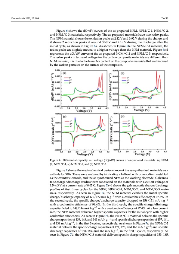
Nanomaterials 2022, 12, 984 7 of 11 Nanomaterials 2022, 12, 984 8 of 12 Figure 6 shows the dQ/dV curves of the as-prepared NFM, NFM/C-1, NFM/C-2, and NFM/C-3 materials, respectively. The as-prepared materials have two redox peaks. The NFM material shows the oxidation peaks at 2.42 V and 3.92 V during the charge, and shows 2 reduction peaks at around 3.50 V and 2.15 V during the discharge after the initial it shows 2 reduction peaks at around 3.50 V and 2.15 V during the discharge after the cycle, as shown in Figure 6a. As shown in Figure 6b, the NFM/C-1 material, the redox initial cycle, as shown in Figure 6a. As shown in Figure 6b, the NFM/C-1 material, the peaks are slightly moved to a higher voltage than the NFM material. Figure 6c,d repre- redox peaks are slightly moved to a higher voltage than the NFM material. Figure 6c,d sents the dQ/dV curves of the as-prepared NCM/C-2 and NFM/C-3, respectively. The re- represents the dQ/dV curves of the as-prepared NCM/C-2 and NFM/C-3, respectively. dox peaks in terms of voltage for the carbon composite materials are different than NFM The redox peaks in terms of voltage for the carbon composite materials are different than material, it is due to the lesser Na content on the composite materials that are hindered by NFM material, it is due to the lesser Na content on the composite materials that are hindered the carbon particles on the surface of the composite. by the carbon particles on the surface of the composite. Fiigurree66..Differentialcapacityvs..vvooltlatgaege(d(dQQ/d/Vd)Vc)ucruvervseosfoafs-apsr-eppraepreadremdamteartiearlsia:l(sa:)(Na)FMNF,M(b,) NFM/C-1, (c) NFM/C-2, and (d) NFM/C-3. (b) NFM/C-1, (c) NFM/C-2, and (d) NFM/C-3. Figure 7 shows the electrochemical performance of the as-synthesized materials as a Figure 7 shows the electrochemical performance of the as-synthesized materials as a cathode for SIBs. These were analyzed by fabricating a half-cell with pure sodium metal foil cathode for SIBs. These were analyzed by fabricating a half-cell with pure sodium metal as the counter electrode, and the as-synthesized NFM as the working electrode. Galvanos- foil as the counter electrode, and the as-synthesized NFM as the working electrode. Gal- tatic charge/discharge studies were conducted on the materials with a cut-off voltage of vanostatic charge/discharge studies were conducted on the materials with a cut-off volt- 1.5–4.3 V at a current rate of 0.05 C. Figure 7a–d shows the galvanostatic charge/discharge age of 1.5–4.3 V at a current rate of 0.05 C. Figure 7a–d shows the galvanostatic charge/dis- profiles of first three cycles for the NFM, NFM/C-1, NFM/C-2, and NFM/C-3 mate- charge profiles of first three cycles for the NFM, NFM/C-1, NFM/C-2, and NFM/C-3 ma- rials, respectively. As seen in Figure 7a, the NFM material exhibits the initial specific terials, respectively. As seen in Figure 7a, the NFM material exhibits the initial specific charge/discharge capacity of 176/172 mA h g−1−1 with a coulombic efficiency of 97.8%. In charge/discharge capacity of 176/172 mA h g with a coulombic efficiency of 97.8%. In the the second cycle, the specific charge/discharge capacity dropped to 156/151 mA−1 h g−1 second cycle, the specific charge/discharge capacity dropped to 156/151 mA h g with a with a coulombic efficiency of 96.4%. In the third cycle, the specific charge/discharge coulombic efficiency of 96.4%. In the third cycle, the specific charge/discharge capacity capacity faded to 148/144 mA h g−1 with a coulombic efficiency of 97.4%. At a low current faded to 148/144 mA h g−1 with a coulombic efficiency of 97.4%. At a low current rate, the rate, the NFM material delivered higher specific capacities for the initial cycle with higher NFM material delivered higher specific capacities for the initial cycle with higher cou- coulombic efficiencies. As seen in Figure 7b, the NFM/C-1 material delivers the specific lombic efficiencies. As seen in Figure 7b, the NFM/C-1 material delivers the specific charge charge capacities of 139, 148, and 141 mA h g−1; and specific discharge capacities of 157, 141, capacities of 139, 148, and 141 mA h g−1; and specific discharge capacities of 157, 141, and and 139 m Ah g−1, in the first 3 cycles, respectively. As shown in Figure 7c, the NFM/C-2 139 m Ah g−1, in the first 3 cycles, respectively. As shown in Figure 7c, the NFM/C-2 ma- material delivers the specific charge capacities of 171, 178, and 166 mA h g−1; and specific terial delivers the specific charge capacities of 171, 178, and 166 mA h g−1; and specific discharge capacities of 188, 169, and 162 mA h g−1, in the first 3 cycles, respectively. As discharge capacities of 188, 169, and 162 mA h g−1, in the first 3 cycles, respectively. As seen in Figure 7d, the NFM/C-3 material delivers specific charge capacities of 153, 165, seen in Figure 7d, the NFM/C-3 material delivers specific charge capacities of 153, 165, and 154 mA h g−1; specific discharge capacities of 169, 157, and 150 mA h g−1 in the first 3PDF Image | NaFe0 Nanocomposite as a Cathode for Sodium-Ion Batteries
PDF Search Title:
NaFe0 Nanocomposite as a Cathode for Sodium-Ion BatteriesOriginal File Name Searched:
nanomaterials-12-00984-v2.pdfDIY PDF Search: Google It | Yahoo | Bing
Salgenx Redox Flow Battery Technology: Salt water flow battery technology with low cost and great energy density that can be used for power storage and thermal storage. Let us de-risk your production using our license. Our aqueous flow battery is less cost than Tesla Megapack and available faster. Redox flow battery. No membrane needed like with Vanadium, or Bromine. Salgenx flow battery
| CONTACT TEL: 608-238-6001 Email: greg@salgenx.com | RSS | AMP |