PDF Publication Title:
Text from PDF Page: 004
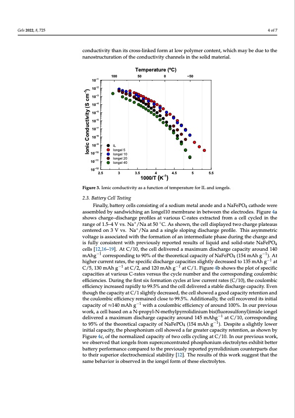
the highest conductivity in the whole temperature range studied. The ionic conductivity Gels 2022, 8, 725 of Iongel10 ranged between 7·10−3 S cm−1 at 80 °C and 2·10−8 S cm−1 at –70 °C. The conduc- tivity decreased up to two orders of magnitude for higher PEGDA content, and the ionic conductivity of Iongel40 ranged between 2.5·10−3 S cm−1 at 80 °C and 3·10−11 S cm−1 at –80 °C. Interestingly, despite the significant differences of several orders of magnitude in the 4 of 7 mechanical modulus, the conductivity only decreased by a factor of 3 in going from Ion- gel10 to Iongel40. Surprisingly, the pure ionic liquid electrolyte displayed a lower ionic conductivity than its cross-linked form at low polymer content, which may be due to the conductivity than its cross-linked form at low polymer content, which may be due to the nanostructuration of the conductivity channels in the solid material. nanostructuration of the conductivity channels in the solid material. 10−1 10−2 10−3 10−4 10−5 10−6 10−7 10−8 10−9 10−10 10−11 Temperature (oC) 100 50 0 −50 IL Iongel 5 Iongel 10 Iongel 20 Iongel 40 10−12 2.5 3 3.5 4 4.5 5 5.5 Figure 3. Ionic conductivity as a function of temperature for IL and iongels. Figure 3. Ionic conductivity as a function of temperature for IL and iongels. 2.3. Battery Cell Testing 2.3. Battery Cell Testing 1000/T (K-1) Finally, battery cells consisting of a sodium metal anode and a NaFePO4 cathode were assemFibnleadllyb,ybsaatntedrwyicehlilnsgcoansIiosntignegl1o0fmaesmodbiruamneminebtaetlwaneeondethaenedleactNroadFeesP.OFi4gcuareth4oadewere shows charge–discharge profiles at various C-rates extracted from a cell cycled in the assembled by sandwiching an Iongel10 membrane in between the electrodes. Figure 4a range of 1.5–4 V vs. Na+/Na at 50 ◦C. As shown, the cell displayed two charge plateaus shows charge–discharge profiles at various C-rates extracted from a cell cycled in the centered on 3 V vs. Na+/Na and a single sloping discharge profile. This asymmetric range of 1.5–4 V vs. Na+/Na at 50 °C. As shown, the cell displayed two charge plateaus voltage is associated with the formation of an intermediate phase during the charge and centered on 3 V vs. Na+/Na and a single sloping discharge profile. This asymmetric voltage is fully consistent with previously reported results of liquid and solid-state NaFePO4 is associated with the formation of an intermediate phase during the charge and is fully cells [12,16–19]. At C/10, the cell delivered a maximum discharge capacity around 140 consist−e1nt with previously reported results of liquid and solid-state NaFePO−41cells [12,16– mAhg corresponding to 90% of the theoretical capacity of NaFePO4 (154 mAh g ). At −1 −1 19]. At C/10, the cell delivered a maximum discharge capacity around 140 mAhg corre- higher current rates, the specific discharge capacities slightly decreased to 135 mAh g at −1 −1 −1 sCp/o5n,d1i3n0gmtoAh90g% oafttCh/e2t,haenodre1t2i0camlAcahpgacitaytoCf/N1.aFiegPuOre44(b15sh4omwAs thegpl)o.tAotf hspigechiefirccurrent capacities at various C-rates versus the cycle number and the corresponding−1coulombic rates, the specific discharge capacities slightly decreased to 135 mAh g at C/5, 130 mAh e−f1ficiencies. During the first−1six formation cycles at low current rates (C/10), the coulombic g at C/2, and 120 mAh g at C/1. Figure 4b shows the plot of specific capacities at various efficiency increased rapidly to 99.5% and the cell delivered a stable discharge capacity. Even C-rates versus the cycle number and the corresponding coulombic efficiencies. During the though the capacity at C/1 slightly decreased, the cell showed a good capacity retention and the coulombic efficiency remained close to 99.5%. Additionally, the cell recovered its initial capacity of ≈140 mAh g−1 with a coulombic efficiency of around 100%. In our previous work, a cell based on a N-propyl-N-methylpyrrolidinium bis(fluorosulfonyl)imide iongel delivered a maximum discharge capacity around 145 mAhg−1 at C/10, corresponding to 95% of the theoretical capacity of NaFePO4 (154 mAh g−1). Despite a slightly lower initial capacity, the phosphonium cell showed a far greater capacity retention, as shown by Figure 4c, of the normalized capacity of two cells cycling at C/10. In our previous work, we observed that iongels from superconcentrated phosphonium electrolytes exhibit better battery performance compared to the previously reported pyrrolidinium counterparts due to their superior electrochemical stability [12]. The results of this work suggest that the same behavior is observed in the iongel form of these electrolytes. Ionic Conductivity (S cm-1)PDF Image | Phosphonium Iongels for Solid-State Sodium Metal Batteries
PDF Search Title:
Phosphonium Iongels for Solid-State Sodium Metal BatteriesOriginal File Name Searched:
gels-08-00725.pdfDIY PDF Search: Google It | Yahoo | Bing
Salgenx Redox Flow Battery Technology: Salt water flow battery technology with low cost and great energy density that can be used for power storage and thermal storage. Let us de-risk your production using our license. Our aqueous flow battery is less cost than Tesla Megapack and available faster. Redox flow battery. No membrane needed like with Vanadium, or Bromine. Salgenx flow battery
| CONTACT TEL: 608-238-6001 Email: greg@salgenx.com | RSS | AMP |