PDF Publication Title:
Text from PDF Page: 003
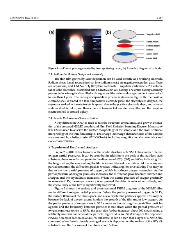
Naannoomaatteerriaialsls2200222, ,1122, ,3x01F8OR PEER REVIEW 3 of 77 Figure 1. (a) Plasma plume generated by laser sputtering target; (b) Assembly diagram of cathode. Figure 1. (a) Plasma plume generated by laser sputtering target; (b) Assembly diagram of cathode. 2.3. Sodium-Ion Battery Design and Assembly 2.3. Sodium-Ion Battery Design and Assembly The thin film grown by laser deposition can be used directly as a working electrode. The thin film grown by laser deposition can be used directly as a working electrode. Sodium sheets (small round slices cut into sodium sheets) are negative electrodes, glass fibers Sodium sheets (small round slices cut into sodium sheets) are negative electrodes, glass are separators, and 1 M NaClO (Ethylene carbonate: Propylene carbonate = 2:1 volume fibers are separators, and 1 M N4aClO4 (Ethylene carbonate: Propylene carbonate = 2:1 vol- ratio) is the electrolyte, assembled into a CR2032 coin cell battery. The entire battery assembly ume ratio) is the electrolyte, assembled into a CR2032 coin cell battery. The entire battery process is done in a glove box filled with argon, and the water and oxygen content is controlled assembly process is done in a glove box filled with argon, and the water and oxygen con- to less than 1 ppm. The battery encapsulation process is shown in Figure 1b: the positive tent is controlled to less than 1 ppm. The battery encapsulation process is shown in Figure electrode shell is placed in a thin film positive electrode piece, the electrolyte is dripped, the 1b: the positive electrode shell is placed in a thin film positive electrode piece, the electro- separator soaked in the electrolyte is spread above the positive electrode sheet, and a metal lyte is dripped, the separator soaked in the electrolyte is spread above the positive elec- sodium sheet is put in, and then a piece of foam nickel is added as a filler, and the negative trode sheet, and a metal sodium sheet is put in, and then a piece of foam nickel is added electrode shell is pressed tightly. as a filler, and the negative electrode shell is pressed tightly. 2.4. Sample Performance Characterization 2.4. Sample Performance Characterization X-ray diffraction (XRD) is used to test the structure, crystallinity, and growth orienta- X-ray diffraction (XRD) is used to test the structure, crystallinity, and growth orien- tion of the prepared NNMO powder and film; Field Emission Scanning Electron Microscopy tation of the prepared NNMO powder and film; Field Emission Scanning Electron Micros- (FESEM) is used to observe the surface morphology of the sample and the cross-sectional copy (FESEM) is used to observe the surface morphology of the sample and the cross- morphology of the thin film sample. The charge–discharge characteristics of the sample sectional morphology of the thin film sample. The charge–discharge characteristics of the are measured by a battery tester (BTS-5V1mA), including magnification characteristics and sample are measured by a battery tester (BTS-5V1mA), including magnification charac- cycle characteristics. teristics and cycle characteristics. 3. Experimental Results and Analysis 3. Experimental Results and Analysis Figure 2 is XRD diffractograms of the crystal structure of NNMO films under different Figure 2 is XRD diffractograms of the crystal structure of NNMO films under differ- oxygen partial pressures. It can be seen that in addition to the peak of the stainless steel seunbtsotrxayteg,etnhepraeratiraelopnrleysstwuroesp.eIatkcsainbtheesdeeirnectthioatnionfa(0d0dl)it:i(o0n02t)oatnhde (p0e0a4k),oinfdthiceatsitnagintlheasts tshteehlesiugbhsttraaloten,gthtehreca-raexoisnalylotnwgotpheafiklsministhinedmirerciti-obnasoefd(0o0rli)e:n(0ta0t2i)oann.dA(t0l0o4w),einrdoixcyagtienng ptharatiathl eprheesisguhrteas,lothneg dthifefrca-catxioisnaploenagk tihs ewfeilamkeirs, indmiceartiitn-bgalsoewd ocryiesntatalltinointy. .ATthloiswmerayoxbye- dgueentpoartthiaellporwespsuaretisa,lthperedsisfufrraectoiofnoxpyegaeknis,wheaickheri,nitnrdoidcuatciensgoloxwygcernysvtacllainictiye.sT.hAismthaey pbaertdiauleptroesthsuerleowof poaxrytgiaelnpgrreasdsuraelloyfionxcryegaesne,s,wthiecdhiifnfrtaroctdiouncepseoaxkybgecnovmaecsanshciaersp.eArsanthde spharrtpiaelr,parensdsuthreocfryosxtyaglleinigtyraidnucraelalyseins.crWeahsens,thepdaifrftriacltipornespseuarkeboefcoxmygesenshgarapdeuralnlyd isnhcarerapseers, taon6d5tPhae, cthryesotxalylgineintyvaincacrnecayseis.suWphperensstehde,pthaertdiaelfepcrteissruerdeuocefdoxayccgoerndignrgaldy,uanlldy tihnecrceraysetasltlioni6t5yPoaf,ththeefiolmxyigsesnigvnaicfiacnacnytlyisismuprporveesdse.d, the defect is reduced accordingly, and Fthigeucreys3taslhlionwitys othf ethseufriflamceisasnidgncirfoicsasn-stleyctiimonparlovFeSdE.M diagram of the NNMO film under different oxygen partial pressures. When the partial pressure of oxygen is 35 Pa, the surface flatness of the film is poor, and a few crystalline particles appear. This may be because the lack of oxygen atoms hinders the growth of the film under low oxygen. As the partial pressure of oxygen rises to 50 Pa, more and more irregular crystalline particles appear, and the boundary between particles is not clear; when the partial pressure of oxygen continues to rise to 65 Pa, the grain size further increases, about 100 nm, showing a relatively uniform nanocrystalline particle. Figure 3d is an FSEM image of the deposited NNMO film cross-section on a SiO2/Si substrate. It can be seen that a layer of NNMO film composed of uniformly densely arranged grains is deposited on the surface of the SiO2/Si substrate, and the thickness of the film is about 550 nm.PDF Image | xcimer Laser-Deposited Na Film Cathode Sodium-Ion Battery
PDF Search Title:
xcimer Laser-Deposited Na Film Cathode Sodium-Ion BatteryOriginal File Name Searched:
nanomaterials-12-03018.pdfDIY PDF Search: Google It | Yahoo | Bing
Salgenx Redox Flow Battery Technology: Salt water flow battery technology with low cost and great energy density that can be used for power storage and thermal storage. Let us de-risk your production using our license. Our aqueous flow battery is less cost than Tesla Megapack and available faster. Redox flow battery. No membrane needed like with Vanadium, or Bromine. Salgenx flow battery
| CONTACT TEL: 608-238-6001 Email: greg@salgenx.com | RSS | AMP |