PDF Publication Title:
Text from PDF Page: 013
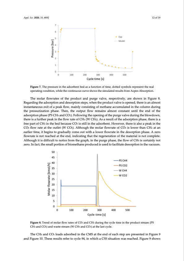
Appl. Sci. 2020, 10, 4692 12 of 19 Figure 7. The pressure in the adsorbent bed as a function of time, dotted symbols represent the real operating condition, while the continuous curve shows the simulated results from Aspen Absorption. The molar flowrates of the product and purge valve, respectively, are shown in Figure 8. Regarding the adsorption and desorption steps, when the product valve is opened, there is an almost instantaneous exit of a peak flow, mainly consisting of methane accumulated in the column during the pressurization phase. Then, the output flow remains almost constant until the end of the adsorption phase (PS CH4 and CO2). Following the opening of the purge valve during the blowdown, there is a further peak in the flow rate of CH4 (W CH4). As a result of the adsorption phase, there is a free part of CH4 in the bed because CO2 is still in the adsorbent. However, there is also a peak in the CO2 flow rate at the outlet (W CO2). Although the molar flowrate of CO2 is lower than CH4 at an earlier time, it begins to gradually come out with a lower flowrate in the desorption phase. A zero flowrate is not reached at the end, indicating that the regeneration of the material is not complete. Although it is difficult to notice from the graph, in the purge phase, the flow of CH4 is certainly not zero. In fact, the small portion of biomethane produced is used to facilitate desorption in the vacuum. Figure 8. Trend of molar flow rates of CO2 and CH4 during the cycle time in the product stream (PS CH4 and CO2) and waste stream (W CH4 and CO2) at the last cycle. The CH4 and CO2 loads adsorbed in the CMS at the end of each step are presented in Figure 9 and Figure 10. These results refer to cycle 94, in which a CSS situation was reached. Figure 9 showsPDF Image | Biogas Six-Step Pressure Swing Adsorption
PDF Search Title:
Biogas Six-Step Pressure Swing AdsorptionOriginal File Name Searched:
applsci-10-04692.pdfDIY PDF Search: Google It | Yahoo | Bing
CO2 Organic Rankine Cycle Experimenter Platform The supercritical CO2 phase change system is both a heat pump and organic rankine cycle which can be used for those purposes and as a supercritical extractor for advanced subcritical and supercritical extraction technology. Uses include producing nanoparticles, precious metal CO2 extraction, lithium battery recycling, and other applications... More Info
Heat Pumps CO2 ORC Heat Pump System Platform More Info
| CONTACT TEL: 608-238-6001 Email: greg@infinityturbine.com | RSS | AMP |