PDF Publication Title:
Text from PDF Page: 010
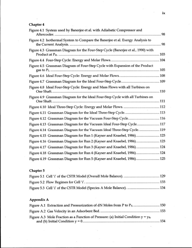
Chapter 4 Figure 4.1 System used by Banerjee et al. with Adiabatic Compressor and Aftercooler Figure 4.2 Isothermal System to Compare the Banerjee et al. Exergy Analysis to the Current Analysis Figure 4.3 Grassman Diagram for the Four-Step Cycle (Banerjee et al., 1990) with Product atPH Figure 4.4 Four-Step Cycle: Energy and Molar Flows Figure 4.5 Grassman Diagram of Four-Step Cycle with Expansion of the Product gas to PL Figure 4.6 Ideal Four-Step Cycle: Energy and Molar Flows Figure 4.7 Grassman Diagram for the Ideal Four-Step Cycle Figure 4.8 Ideal Four-Step Cycle: Energy and Mass Flows with all Turbines on One Shaft Figure 4.9 Grassman Diagram for the Ideal Four-Step Cycle with all Turbines on One Shaft Figure 4.10 Ideal Three-Step Cycle: Energy and Molar Flows Figure 4.11 Grassman Diagram for the Ideal Three-Step Cycle Figure 4.12 Grassman Diagram for the Vacuum Four-Step Cycle Figure 4.13 Grassman Diagram for the Vacuum Ideal Four-Step Cycle Figure 4.14 Grassman Diagram for the Vacuum Ideal Three-Step Cycle Figure 4.15 Grassman Diagram for Run 1 (Kayser and Knaebel, 1986) Figure 4.16 Grassman Diagram for Run 2 (Kayser and Knaebel, 1986) Figure 4.17 Grassman Diagram for Run 3 (Kayser and Knaebel, 1986) Figure 4.18 Grassman Diagram for Run 4 (Kayser and Knaebel, 1986) Figure 4.19 Grassman Diagram for Run 5 (Kayser and Knaebel, 1986) Chapter 5 Figure 5.1 Cell 'i' of the CSTR Model (Overall Mole Balance) Figure 5.2 Flow Regimes for Cell 'i Figure 5.3 Cell 'i' of the CSTR Model (Species A Mole Balance) Appendix A Figure A.l Extraction and Pressurization of d N Moles from P to Px Figure A.2 Gas Velocity in an Adsorbent Bed Figure A.3 Mole Fraction as a Function of Pressure: (a) Initial Condition y = yB, and (b) Initial Condition y = 0 98 98 103 104 105 108 109 110 I l l 112 113 116 117 119 123 123 124 124 125 129 133 134 150 153 154PDF Image | Energy Efficiency of Gas Separation Pressure Swing Adsorption

PDF Search Title:
Energy Efficiency of Gas Separation Pressure Swing AdsorptionOriginal File Name Searched:
ubc_1997-0009.pdfDIY PDF Search: Google It | Yahoo | Bing
CO2 Organic Rankine Cycle Experimenter Platform The supercritical CO2 phase change system is both a heat pump and organic rankine cycle which can be used for those purposes and as a supercritical extractor for advanced subcritical and supercritical extraction technology. Uses include producing nanoparticles, precious metal CO2 extraction, lithium battery recycling, and other applications... More Info
Heat Pumps CO2 ORC Heat Pump System Platform More Info
| CONTACT TEL: 608-238-6001 Email: greg@infinityturbine.com | RSS | AMP |