PDF Publication Title:
Text from PDF Page: 003
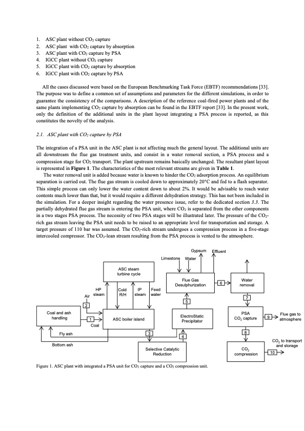
1. ASC plant without CO2 capture 2. ASC plant with CO2 capture by absorption 3. ASC plant with CO2 capture by PSA 4. IGCC plant without CO2 capture 5. IGCC plant with CO2 capture by absorption 6. IGCC plant with CO2 capture by PSA All the cases discussed were based on the European Benchmarking Task Force (EBTF) recommendations [33]. The purpose was to define a common set of assumptions and parameters for the different simulations, in order to guarantee the consistency of the comparisons. A description of the reference coal-fired power plants and of the same plants implementing CO2 capture by absorption can be found in the EBTF report [33]. In the present work, only the definition of the additional units in the plant layout integrating a PSA process is reported, as this constitutes the novelty of the analysis. 2.1. ASC plant with CO2 capture by PSA The integration of a PSA unit in the ASC plant is not affecting much the general layout. The additional units are all downstream the flue gas treatment units, and consist in a water removal section, a PSA process and a compression stage for CO2 transport. The plant upstream remains basically unchanged. The resultant plant layout is represented in Figure 1. The characteristics of the most relevant streams are given in Table 1. The water removal unit is added because water is known to hinder the CO2 adsorption process. An equilibrium separation is carried out. The flue gas stream is cooled down to approximately 20°C and fed to a flash separator. This simple process can only lower the water content down to about 2%. It would be advisable to reach water contents much lower than that, but it would require a different dehydration strategy. This has not been included in the simulation. For a deeper insight regarding the water presence issue, refer to the dedicated section 3.3. The partially dehydrated flue gas stream is entering the PSA unit, where CO2 is separated from the other components in a two stages PSA process. The necessity of two PSA stages will be illustrated later. The pressure of the CO2- rich gas stream leaving the PSA unit needs to be raised to an appropriate level for transportation and storage. A target pressure of 110 bar was assumed. The CO2-rich stream undergoes a compression process in a five-stage intercooled compressor. The CO2-lean stream resulting from the PSA process is vented to the atmosphere. ASC steam turbine cycle Flue Gas Desulphurization Water removal HP Air steam 2 Coal Cold IP Feed R/H steam water 3 Gypsum Limestone Water 5 4 Effluent 6 7 8 9 Flue gas to atmosphere CO2 to transport and storage 10 Coal and ash handling 1 ASC boiler island ElectroStatic Precipitator PSA CO2 capture Fly ash Bottom ash Selective Catalytic Reduction CO2 compression Figure 1. ASC plant with integrated a PSA unit for CO2 capture and a CO2 compression unit.PDF Image | Evaluating Pressure Swing Adsorption as a CO2 separation technique in coal-fired
PDF Search Title:
Evaluating Pressure Swing Adsorption as a CO2 separation technique in coal-firedOriginal File Name Searched:
PSA-coal-fired-plants.pdfDIY PDF Search: Google It | Yahoo | Bing
CO2 Organic Rankine Cycle Experimenter Platform The supercritical CO2 phase change system is both a heat pump and organic rankine cycle which can be used for those purposes and as a supercritical extractor for advanced subcritical and supercritical extraction technology. Uses include producing nanoparticles, precious metal CO2 extraction, lithium battery recycling, and other applications... More Info
Heat Pumps CO2 ORC Heat Pump System Platform More Info
| CONTACT TEL: 608-238-6001 Email: greg@infinityturbine.com | RSS | AMP |