PDF Publication Title:
Text from PDF Page: 014
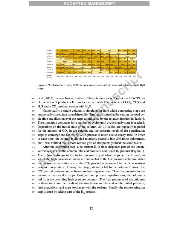
Column 1 Column 2 Column 3 Column 4 Column 5 Column 6 Column 7 Column 8 Column 9 Relative duration purge 1/18 1/18 1/18 1/18 1/18 1/18 1/18 1/18 1/18 1/18 1/18 1/18 1/18 1/18 1/18 1/18 1/18 1/18 peq3 rinse adsorption peq2 purge peq1 peq2 purge peq3 peq3 rinse peq2 dep peq1 peq1 peq2 adsorption rep purge peq3 peq3 dep adsorption peq1 peq3 peq2 purge peq1 rinse adsorption rep peq3 peq1 peq2 peq2 peq1 peq3 purge rinse rep peq1 peq3 rep peq2 peq1 peq3 adsorption rep peq2 peq1 adsorption rep rinse peq1 rinse peq2 peq3 peq1 rinse dep peq2 peq3 peq1 dep peq2 purge peq3 dep purge peq3 peq2 dep peq1 dep peq3 dep purge peq3 peq2 peq1 rep peq2 adsorption rinse peq1 peq2 rep adsorption rinse peq1 peq2 dep purge peq3 peq2 adsorption peq3 peq1 rep adsorption Figure 3: 9 columns for 11-step SEWGS cycle with co-current H2O rinse and counter-current H2O purge 264 et al., 2013). In conclusion, neither of these impurities will upset the SEWGS cy- 265 cle, which will produce a H2 product stream with low contents of CO2, COS and 266 H2 S and a CO2 product stream with H2 S. 267 Numerically, a single column is simulated in time while connecting steps are 268 temporarily stored in a spreadsheet file. Timing is controlled by setting the total cy- 269 cle time and division over the steps as indicated by the relative duration in Table 4. 270 The simulation continues for a number of cycles until cyclic steady state is reached. 271 Depending on the initial state of the column, 20–30 cycles are typically required 272 for the amount of CO2 in the column and the pressure levels of the equalisation 273 steps to converge and for the SEWGS process to reach cyclic steady state. In order 274 to save time, the column is divided relatively coarsely into 200 finite differences, 275 but it was verified that a more refined grid of 400 points yielded the same results. 276 After the adsorption step, a co-current H2O rinse displaces part of the uncon- 277 verted syngas near the column inlet and produces additional H2 product (Figure 1). 278 Then, three subsequent top to top pressure equalisation steps are performed, in 279 which the high pressure columns are connected to the low pressure columns. After 280 the pressure equalisation steps, the CO2 product is recovered in the depressurisa- 281 tion and purge steps. During the purge, steam is fed to the column to lower the 282 CO2 partial pressure and enhance sorbent regeneration. Then, the pressure in the 283 column is increased in steps. First, in three pressure equalisations, the column is 284 fed from the providing high pressure columns. The final pressures of the columns 285 in these steps are the result of the simulation and depend on the initial pressure, 286 feed conditions, and mass exchange with the sorbent. Finally, the repressurisation 287 step is done by taking part of the H2 product. 12PDF Image | High-temperature pressure swing adsorption cycle design for sorption
PDF Search Title:
High-temperature pressure swing adsorption cycle design for sorptionOriginal File Name Searched:
high-temperature-pressure-swing-adsorption.pdfDIY PDF Search: Google It | Yahoo | Bing
CO2 Organic Rankine Cycle Experimenter Platform The supercritical CO2 phase change system is both a heat pump and organic rankine cycle which can be used for those purposes and as a supercritical extractor for advanced subcritical and supercritical extraction technology. Uses include producing nanoparticles, precious metal CO2 extraction, lithium battery recycling, and other applications... More Info
Heat Pumps CO2 ORC Heat Pump System Platform More Info
| CONTACT TEL: 608-238-6001 Email: greg@infinityturbine.com | RSS | AMP |