PDF Publication Title:
Text from PDF Page: 010
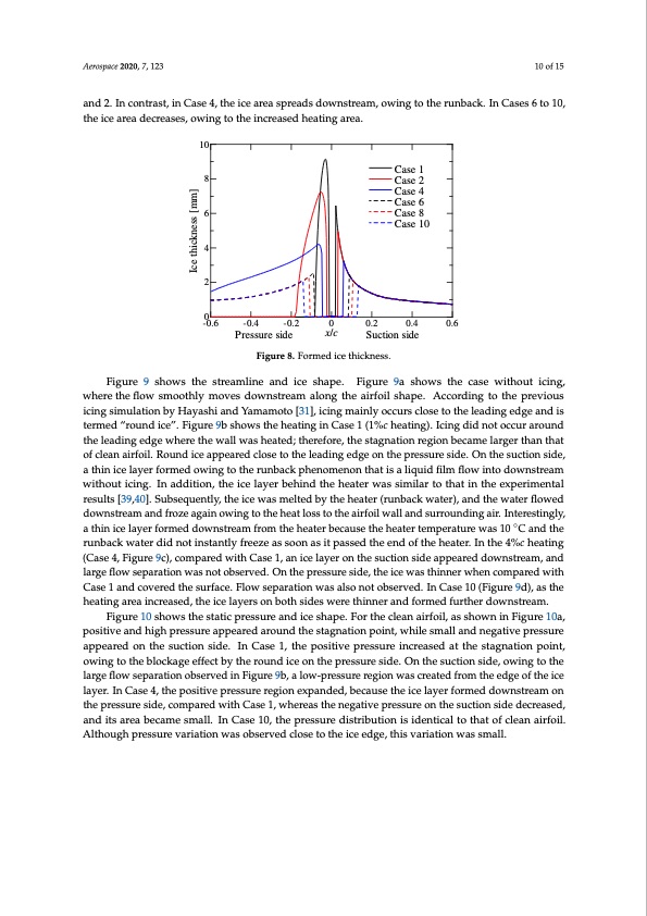
Aerospace 2020, 7, 123 10 of 15 and 2. In contrast, in Case 4, the ice area spreads downstream, owing to the runback. In Cases 6 to 10, the ice area decreases, owing to the increased heating area. 10 8 6 4 2 0 -0.6 -0.4 -0.2 x/c Suction side Figure 8. Formed ice thickness. Figure 9 shows the streamline and ice shape. Figure 9a shows the case without icing, where the flow smoothly moves downstream along the airfoil shape. According to the previous icing simulation by Hayashi and Yamamoto [31], icing mainly occurs close to the leading edge and is termed “round ice”. Figure 9b shows the heating in Case 1 (1%c heating). Icing did not occur around the leading edge where the wall was heated; therefore, the stagnation region became larger than that of clean airfoil. Round ice appeared close to the leading edge on the pressure side. On the suction side, a thin ice layer formed owing to the runback phenomenon that is a liquid film flow into downstream without icing. In addition, the ice layer behind the heater was similar to that in the experimental results [39,40]. Subsequently, the ice was melted by the heater (runback water), and the water flowed downstream and froze again owing to the heat loss to the airfoil wall and surrounding air. Interestingly, a thin ice layer formed downstream from the heater because the heater temperature was 10 ◦C and the runback water did not instantly freeze as soon as it passed the end of the heater. In the 4%c heating (Case 4, Figure 9c), compared with Case 1, an ice layer on the suction side appeared downstream, and large flow separation was not observed. On the pressure side, the ice was thinner when compared with Case 1 and covered the surface. Flow separation was also not observed. In Case 10 (Figure 9d), as the heating area increased, the ice layers on both sides were thinner and formed further downstream. Figure 10 shows the static pressure and ice shape. For the clean airfoil, as shown in Figure 10a, positive and high pressure appeared around the stagnation point, while small and negative pressure appeared on the suction side. In Case 1, the positive pressure increased at the stagnation point, owing to the blockage effect by the round ice on the pressure side. On the suction side, owing to the large flow separation observed in Figure 9b, a low-pressure region was created from the edge of the ice layer. In Case 4, the positive pressure region expanded, because the ice layer formed downstream on the pressure side, compared with Case 1, whereas the negative pressure on the suction side decreased, and its area became small. In Case 10, the pressure distribution is identical to that of clean airfoil. Although pressure variation was observed close to the ice edge, this variation was small. Case 1 Case 2 Case 4 Case 6 Case 8 Case 10 Pressure side 0 0.2 0.4 0.6 Ice thickness [mm]PDF Image | Anti-Icing Electric Heaters for Icing on the NACA 0012 Airfoil
PDF Search Title:
Anti-Icing Electric Heaters for Icing on the NACA 0012 AirfoilOriginal File Name Searched:
aerospace-07-00123.pdfDIY PDF Search: Google It | Yahoo | Bing
NFT (Non Fungible Token): Buy our tech, design, development or system NFT and become part of our tech NFT network... More Info
IT XR Project Redstone NFT Available for Sale: NFT for high tech turbine design with one part 3D printed counter-rotating energy turbine. Be part of the future with this NFT. Can be bought and sold but only one design NFT exists. Royalties go to the developer (Infinity) to keep enhancing design and applications... More Info
Infinity Turbine IT XR Project Redstone Design: NFT for sale... NFT for high tech turbine design with one part 3D printed counter-rotating energy turbine. Includes all rights to this turbine design, including license for Fluid Handling Block I and II for the turbine assembly and housing. The NFT includes the blueprints (cad/cam), revenue streams, and all future development of the IT XR Project Redstone... More Info
Infinity Turbine ROT Radial Outflow Turbine 24 Design and Worldwide Rights: NFT for sale... NFT for the ROT 24 energy turbine. Be part of the future with this NFT. This design can be bought and sold but only one design NFT exists. You may manufacture the unit, or get the revenues from its sale from Infinity Turbine. Royalties go to the developer (Infinity) to keep enhancing design and applications... More Info
Infinity Supercritical CO2 10 Liter Extractor Design and Worldwide Rights: The Infinity Supercritical 10L CO2 extractor is for botanical oil extraction, which is rich in terpenes and can produce shelf ready full spectrum oil. With over 5 years of development, this industry leader mature extractor machine has been sold since 2015 and is part of many profitable businesses. The process can also be used for electrowinning, e-waste recycling, and lithium battery recycling, gold mining electronic wastes, precious metals. CO2 can also be used in a reverse fuel cell with nafion to make a gas-to-liquids fuel, such as methanol, ethanol and butanol or ethylene. Supercritical CO2 has also been used for treating nafion to make it more effective catalyst. This NFT is for the purchase of worldwide rights which includes the design. More Info
NFT (Non Fungible Token): Buy our tech, design, development or system NFT and become part of our tech NFT network... More Info
Infinity Turbine Products: Special for this month, any plans are $10,000 for complete Cad/Cam blueprints. License is for one build. Try before you buy a production license. May pay by Bitcoin or other Crypto. Products Page... More Info
| CONTACT TEL: 608-238-6001 Email: greg@infinityturbine.com | RSS | AMP |