PDF Publication Title:
Text from PDF Page: 007
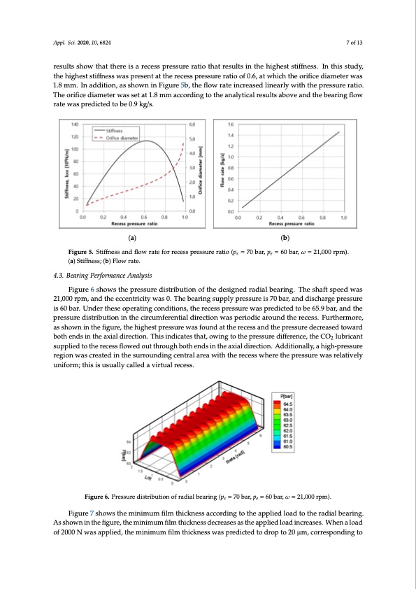
Appl. Sci. 2020, 10, x FOR PEER REVIEW 7 of 14 Figure 5 shows the bearing stiffness and flow rate according to the recess pressure ratio. In this study, two translational degrees of freedom were considered for the rotor, and the bearing stiffness Figure 5 shows the bearing stiffness and flow rate according to the recess pressure ratio. In this described in Figure 5a indicates the value of kxx as defined in the coordinate system shown in Figure study, two translational degrees of freedom were considered for the rotor, and the bearing stiffness 2. Figure 5a also shows the orifice diameter corresponding to the recess pressure ratio. The analytical Adpepslc. rSicbi.e2d02i0n, 1F0,ig68u2r4e 5a indicates the value of kxx as defined in the coordinate system shown in Fi7gouf r1e3 results show that there is a recess pressure ratio that results in the highest stiffness. In this study, the 2. Figure 5a also shows the orifice diameter corresponding to the recess pressure ratio. The analytical highest stiffness was present at the recess pressure ratio of 0.6, at which the orifice diameter was 1.8 results show that there is a recess pressure ratio that results in the highest stiffness. In this study, the mremsu.lItns ashdodwitiothna,tasthsehroewisnainreFciegsusrepr5ebs,stuhrefrloawtiorathteatinrcerseualstsedinlitnheearhlyigwheitsht sthtieffpneresss.uIrnetrhaitsios.tTuhdey, highest stiffness was present at the recess pressure ratio of 0.6, at which the orifice diameter was 1.8 otrhieficheigdhieasmtesteiffrnweasssweatsatp1re.8semnmtaatctchoerrdeicnegsstoptrheessaunraelyratitcioalorfe0su.6l,tsatawbohviechanthdethoreifibeceardiniagmfleotwerrwataes mm. In addition, as shown in Figure 5b, the flow rate increased linearly with the pressure ratio. The w1.a8smpmred. iIcnteaddtoitbioen0,.9asksgh/so.wn in Figure 5b, the flow rate increased linearly with the pressure ratio. orifice diameter was set at 1.8 mm according to the analytical results above and the bearing flow rate The orifice diameter was set at 1.8 mm according to the analytical results above and the bearing flow was predicted to be 0.9 kg/s. rate was predicted to be 0.9 kg/s. (a) (b) Figure 5. Stiffness and(afl)ow rate for recess pressure ratio (ps = 70 bar, pe = 60 b(abr), ω = 21,000 rpm). (a) Stiffness; (b) Flow rate. Figure5.Sttiiffffnessandfflloowrraatetefoforrrerecceesssppreressusurereraratitoio(p(sp==707b0abr,apr,ep=6=06b0arb,aωr,=ω21=,02010,0r0p0mr)p.m(a). (Sat)ifSfntieffsnse;s(bs;)(Fbl)oFwlorwatera.te. 4.3. Bearing Performance Analysis 4.3. Bearing Performance Analysis 4.3. BFeigaruinreg 6PesrhforwmsanthceApnraelsyssuisre distribution of the designed radial bearing. The shaft speed was 21,000 rpm, and the eccentricity was 0. The bearing supply pressure is 70 bar, and discharge pressure Figure 6 shows the pressure distribution of the designed radial bearing. The shaft speed was Figure 6 shows the pressure distribution of the designed radial bearing. The shaft speed was is 60 bar. Under these operating conditions, the recess pressure was predicted to be 65.9 bar, and the 21,000 rpm, and the eccentricity was 0. The bearing supply pressure is 70 bar, and discharge pressure 21,000 rpm, and the eccentricity was 0. The bearing supply pressure is 70 bar, and discharge pressure pressure distribution in the circumferential direction was periodic around the recess. Furthermore, is 60 bar. Under these operating conditions, the recess pressure was predicted to be 65.9 bar, and the is 60 bar. Under these operating conditions, the recess pressure was predicted to be 65.9 bar, and the as shown in the figure, the highest pressure was found at the recess and the pressure decreased pressure distribution in the circumferential direction was periodic around the recess. Furthermore, pressure distribution in the circumferential direction was periodic around the recess. Furthermore, toward both ends in the axial direction. This indicates that, owing to the pressure difference, the CO2 as shown in the figure, the highest pressure was found at the recess and the pressure decreased toward as shown in the figure, the highest pressure was found at the recess and the pressure decreased lubricant supplied to the recess flowed out through both ends in the axial direction. Additionally, a both ends in the axial direction. This indicates that, owing to the pressure difference, the CO2 lubricant toward both ends in the axial direction. This indicates that, owing to the pressure difference, the CO2 high-pressure region was created in the surrounding central area with the recess where the pressure supplied to the recess flowed out through both ends in the axial direction. Additionally, a high-pressure lubricant supplied to the recess flowed out through both ends in the axial direction. Additionally, a was relatively uniform; this is usually called a virtual recess. region was created in the surrounding central area with the recess where the pressure was relatively high-pressure region was created in the surrounding central area with the recess where the pressure uniform; this is usually called a virtual recess. was relatively uniform; this is usually called a virtual recess. se Figure6.Pressuredistributionofradialbearing(p =70bar,p =60bar,ω=21,000rpm). se Figure 6. Pressure distribution of radial bearing (ps = 70 bar, pe = 60 bar, ω = 21,000 rpm). Figure 6. Pressure distribution of radial bearing (ps = 70 bar, pe = 60 bar, ω = 21,000 rpm). Figure 7 shows the minimum film thickness according to the applied load to the radial bearing. As shown in the figure, the minimum film thickness decreases as the applied load increases. When a load of 2000 N was applied, the minimum film thickness was predicted to drop to 20 μm, corresponding toPDF Image | Development of Pump-Drive Turbine Module Super CO2 Application
PDF Search Title:
Development of Pump-Drive Turbine Module Super CO2 ApplicationOriginal File Name Searched:
applsci-10-06824.pdfDIY PDF Search: Google It | Yahoo | Bing
NFT (Non Fungible Token): Buy our tech, design, development or system NFT and become part of our tech NFT network... More Info
IT XR Project Redstone NFT Available for Sale: NFT for high tech turbine design with one part 3D printed counter-rotating energy turbine. Be part of the future with this NFT. Can be bought and sold but only one design NFT exists. Royalties go to the developer (Infinity) to keep enhancing design and applications... More Info
Infinity Turbine IT XR Project Redstone Design: NFT for sale... NFT for high tech turbine design with one part 3D printed counter-rotating energy turbine. Includes all rights to this turbine design, including license for Fluid Handling Block I and II for the turbine assembly and housing. The NFT includes the blueprints (cad/cam), revenue streams, and all future development of the IT XR Project Redstone... More Info
Infinity Turbine ROT Radial Outflow Turbine 24 Design and Worldwide Rights: NFT for sale... NFT for the ROT 24 energy turbine. Be part of the future with this NFT. This design can be bought and sold but only one design NFT exists. You may manufacture the unit, or get the revenues from its sale from Infinity Turbine. Royalties go to the developer (Infinity) to keep enhancing design and applications... More Info
Infinity Supercritical CO2 10 Liter Extractor Design and Worldwide Rights: The Infinity Supercritical 10L CO2 extractor is for botanical oil extraction, which is rich in terpenes and can produce shelf ready full spectrum oil. With over 5 years of development, this industry leader mature extractor machine has been sold since 2015 and is part of many profitable businesses. The process can also be used for electrowinning, e-waste recycling, and lithium battery recycling, gold mining electronic wastes, precious metals. CO2 can also be used in a reverse fuel cell with nafion to make a gas-to-liquids fuel, such as methanol, ethanol and butanol or ethylene. Supercritical CO2 has also been used for treating nafion to make it more effective catalyst. This NFT is for the purchase of worldwide rights which includes the design. More Info
NFT (Non Fungible Token): Buy our tech, design, development or system NFT and become part of our tech NFT network... More Info
Infinity Turbine Products: Special for this month, any plans are $10,000 for complete Cad/Cam blueprints. License is for one build. Try before you buy a production license. May pay by Bitcoin or other Crypto. Products Page... More Info
| CONTACT TEL: 608-238-6001 Email: greg@infinityturbine.com | RSS | AMP |