PDF Publication Title:
Text from PDF Page: 003
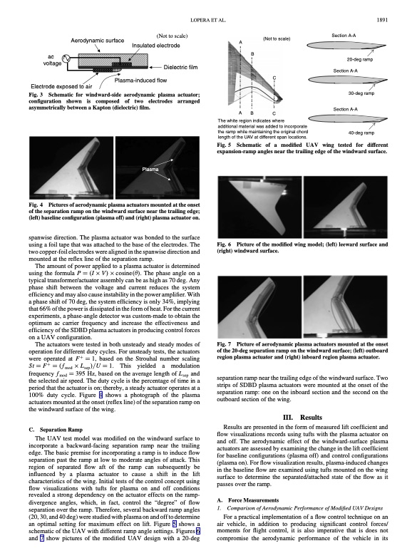
Aerodynamic surface A (Not to scale) Insulated electrode Dielectric film Plasma-induced flow (Not to scale) Section A-A LOPERA ET AL. 1891 ac voltage Electrode exposed to air B ABC The white region indicates where additional material was added to incorporate the ramp while maintaining the original chord length of the UAV at different span locations. 20-deg ramp Section A-A 30-deg ramp Section A-A 40-deg ramp Fig. 3 Schematic for windward-side aerodynamic plasma actuator; configuration shown is composed of two electrodes arranged asymmetrically between a Kapton (dielectric) film. Plasma Fig. 5 Schematic of a modified UAV wing tested for different expansion-ramp angles near the trailing edge of the windward surface. C Fig. 4 of the separation ramp on the windward surface near the trailing edge; (left) baseline configuration (plasma off) and (right) plasma actuator on. spanwise direction. The plasma actuator was bonded to the surface using a foil tape that was attached to the base of the electrodes. The two copper-foil electrodes were aligned in the spanwise direction and mounted at the reflex line of the separation ramp. The amount of power applied to a plasma actuator is determined using the formula P I V cosine. The phase angle on a typical transformer/actuator assembly can be as high as 70 deg. Any phase shift between the voltage and current reduces the system efficiency and may also cause instability in the power amplifier. With a phase shift of 70 deg, the system efficiency is only 34%, implying that 66% of the power is dissipated in the form of heat. For the current experiments, a phase-angle detector was custom-made to obtain the optimum ac carrier frequency and increase the effectiveness and efficiency of the SDBD plasma actuators in producing control forces on a UAV configuration. The actuators were tested in both unsteady and steady modes of operation for different duty cycles. For unsteady tests, the actuators were operated at F 1, based on the Strouhal number scaling St F fmod Lsep=U 1. This yielded a modulation frequency fmod 395 Hz, based on the average length of Lsep and the selected air speed. The duty cycle is the percentage of time in a period that the actuator is on; thereby, a steady actuator operates at a 100% duty cycle. Figure 4 shows a photograph of the plasma actuators mounted at the onset (reflex line) of the separation ramp on the windward surface of the wing. Pictures of aerodynamic plasma actuators mounted at the onset Picture of the modified wing model; (left) leeward surface and Fig. 6 (right) windward surface. C. Separation Ramp The UAV test model was modified on the windward surface to incorporate a backward-facing separation ramp near the trailing edge. The basic premise for incorporating a ramp is to induce flow separation past the ramp at low to moderate angles of attack. This region of separated flow aft of the ramp can subsequently be influenced by a plasma actuator to cause a shift in the lift characteristics of the wing. Initial tests of the control concept using flow visualizations with tufts for plasma on and off conditions revealed a strong dependency on the actuator effects on the ramp- divergence angles, which, in fact, control the “degree” of flow separation over the ramp. Therefore, several backward ramp angles (20, 30, and 40 deg) were studied with plasma on and off to determine an optimal setting for maximum effect on lift. Figure 5 shows a schematic of the UAV with different ramp angle settings. Figures 6 and 7 show pictures of the modified UAV design with a 20-deg A. 1. Force Measurements Comparison of Aerodynamic Performance of Modified UAV Designs Fig. 7 of the 20-deg separation ramp on the windward surface; (left) outboard region plasma actuator and (right) inboard region plasma actuator. separation ramp near the trailing edge of the windward surface. Two strips of SDBD plasma actuators were mounted at the onset of the separation ramp: one on the inboard section and the second on the outboard section of the wing. III. Results Results are presented in the form of measured lift coefficient and flow visualizations records using tufts with the plasma actuator on and off. The aerodynamic effect of the windward-surface plasma actuators are assessed by examining the change in the lift coefficient for baseline configurations (plasma off) and control configurations (plasma on). For flow visualization results, plasma-induced changes in the baseline flow are examined using tufts mounted on the wing surface to determine the separated/attached state of the flow as it passes over the ramp. Picture of aerodynamic plasma actuators mounted at the onset For a practical implementation of a flow control technique on an air vehicle, in addition to producing significant control forces/ moments for flight control, it is also imperative that is does not compromise the aerodynamic performance of the vehicle in itsPDF Image | Aerodynamic Control Using Windward-Surface Plasma Actuators on a Separation Ramp
PDF Search Title:
Aerodynamic Control Using Windward-Surface Plasma Actuators on a Separation RampOriginal File Name Searched:
JA-2007-Windward Plasma UCAV Lift Control.pdfDIY PDF Search: Google It | Yahoo | Bing
NFT (Non Fungible Token): Buy our tech, design, development or system NFT and become part of our tech NFT network... More Info
IT XR Project Redstone NFT Available for Sale: NFT for high tech turbine design with one part 3D printed counter-rotating energy turbine. Be part of the future with this NFT. Can be bought and sold but only one design NFT exists. Royalties go to the developer (Infinity) to keep enhancing design and applications... More Info
Infinity Turbine IT XR Project Redstone Design: NFT for sale... NFT for high tech turbine design with one part 3D printed counter-rotating energy turbine. Includes all rights to this turbine design, including license for Fluid Handling Block I and II for the turbine assembly and housing. The NFT includes the blueprints (cad/cam), revenue streams, and all future development of the IT XR Project Redstone... More Info
Infinity Turbine ROT Radial Outflow Turbine 24 Design and Worldwide Rights: NFT for sale... NFT for the ROT 24 energy turbine. Be part of the future with this NFT. This design can be bought and sold but only one design NFT exists. You may manufacture the unit, or get the revenues from its sale from Infinity Turbine. Royalties go to the developer (Infinity) to keep enhancing design and applications... More Info
Infinity Supercritical CO2 10 Liter Extractor Design and Worldwide Rights: The Infinity Supercritical 10L CO2 extractor is for botanical oil extraction, which is rich in terpenes and can produce shelf ready full spectrum oil. With over 5 years of development, this industry leader mature extractor machine has been sold since 2015 and is part of many profitable businesses. The process can also be used for electrowinning, e-waste recycling, and lithium battery recycling, gold mining electronic wastes, precious metals. CO2 can also be used in a reverse fuel cell with nafion to make a gas-to-liquids fuel, such as methanol, ethanol and butanol or ethylene. Supercritical CO2 has also been used for treating nafion to make it more effective catalyst. This NFT is for the purchase of worldwide rights which includes the design. More Info
NFT (Non Fungible Token): Buy our tech, design, development or system NFT and become part of our tech NFT network... More Info
Infinity Turbine Products: Special for this month, any plans are $10,000 for complete Cad/Cam blueprints. License is for one build. Try before you buy a production license. May pay by Bitcoin or other Crypto. Products Page... More Info
| CONTACT TEL: 608-238-6001 Email: greg@infinityturbine.com | RSS | AMP |