PDF Publication Title:
Text from PDF Page: 004
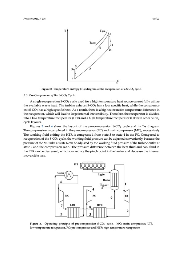
Processes 2020, 8, x FOR PEER REVIEW Processes 2020, 8, 216 Figure 2. Temperature-entropy (T-s) diagram of the recuperation of a S-CO2 cycle. Figure 2. Temperature-entropy (T-s) diagram of the recuperation of a S-CO2 cycle. 4 of 23 Processes 2020, 8, x FOR PEER REVIEW 4 of 23 2.3. Pre-Compression of the S-CO2 Cycle Figure 2. Temperature-entropy (T-s) diagram of the recuperation of a S-CO2 cycle. 2.3. Pre-Compression of the S-CO2 Cycle A single recuperation S-CO2 cycle used for a high temperature heat source cannot fully utilize AsinglerecuperationS-CO cycleusedforahightemperatureheatsourcecannotfullyutilize 2.3. Pre-Compression of the S-CO2 2 Cycle the available waste heat. The turbine exhaust S-CO2 has a low specific heat, while the compressor 4 of 23 the available waste heat. The turbine exhaust S-CO2 has a low specific heat, while the compressor exit S-CO2 has a high specific heat. As a result, there is a big heat transfer temperature difference in A single recuperation S-CO2 cycle used for a high temperature heat source cannot fully utilize exit S-CO2 has a high specific heat. As a result, there is a big heat transfer temperature difference in the recuperator, which will lead to large internal irreversibility. Therefore, the recuperator is the available waste heat. The turbine exhaust S-CO2 has a low specific heat, while the compressor the recuperator, which will lead to large internal irreversibility. Therefore, the recuperator is divided divided into a low temperature recuperator (LTR) and a high temperature recuperator (HTR) in exit S-CO2 has a high specific heat. As a result, there is a big heat transfer temperature difference in into a low temperature recuperator (LTR) and a high temperature recuperator (HTR) in other S-CO2 other S-CO2 cycle layouts. the recuperator, which will lead to large internal irreversibility. Therefore, the recuperator is cycle layouts. Figures 3 and 4 show the layout of the pre-compression S-CO2 cycle and its T-s diagram. The divided into a low temperature recuperator (LTR) and a high temperature recuperator (HTR) in Figures 3 and 4 show the layout of the pre-compression S-CO2 cycle and its T-s diagram. compression is completed in the pre-compressor (PC) and main compressor (MC), successively. The other S-CO2 cycle layouts. The compression is completed in the pre-compressor (PC) and main compressor (MC), successively. working fluid exiting the HTR is compressed from state 3 to state 4 in the PC. Compared to Figures 3 and 4 show the layout of the pre-compression S-CO2 cycle and its T-s diagram. The The working fluid exiting the HTR is compressed from state 3 to state 4 in the PC. Compared to recuperation of the S-CO2 cycle, the working fluid pressure can be adjusted conveniently, because compression is completed in the pre-compressor (PC) and main compressor (MC), successively. The recuperation of the S-CO2 cycle, the working fluid pressure can be adjusted conveniently, because the the pressure of the MC inlet at state 6 can be adjusted by the working fluid pressure of the turbine working fluid exiting the HTR is compressed from state 3 to state 4 in the PC. Compared to pressure of the MC inlet at state 6 can be adjusted by the working fluid pressure of the turbine outlet at outlet at state 2 and the compression ratio. The pressure difference between the heat fluid and cool recuperation of the S-CO2 cycle, the working fluid pressure can be adjusted conveniently, because state 2 and the compression ratio. The pressure difference between the heat fluid and cool fluid in fluid in the LTR can be decreased, which can reduce the pinch point in the heater and decrease the the pressure of the MC inlet at state 6 can be adjusted by the working fluid pressure of the turbine the LTR can be decreased, which can reduce the pinch point in the heater and decrease the internal internal irreversible loss. outlet at state 2 and the compression ratio. The pressure difference between the heat fluid and cool irreversible loss. fluid in the LTR can be decreased, which can reduce the pinch point in the heater and decrease the internal irreversible loss. Figure 3. Operating principle of pre-compression S-CO2 cycle. MC: main compressor, LTR: Fliogwurtem3.peOrpateurraetirnegcupreinractioprl,ePoCf:pre-compressoiornanSd-CHOT2Rc:yhcilgeh.tMemCp:emratiunrecoremcpurpesrsaotro,r.LTR:low temperature recuperator, PC: pre-compressor and HTR: high temperature recuperator. Figure 3. Operating principle of pre-compression S-CO2 cycle. MC: main compressor, LTR: low temperature recuperator, PC: pre-compressor and HTR: high temperature recuperator.PDF Image | Supercritical CO2 Cycle for ICE Waste Heat Recovery
PDF Search Title:
Supercritical CO2 Cycle for ICE Waste Heat RecoveryOriginal File Name Searched:
processes-08-00216-v2.pdfDIY PDF Search: Google It | Yahoo | Bing
NFT (Non Fungible Token): Buy our tech, design, development or system NFT and become part of our tech NFT network... More Info
IT XR Project Redstone NFT Available for Sale: NFT for high tech turbine design with one part 3D printed counter-rotating energy turbine. Be part of the future with this NFT. Can be bought and sold but only one design NFT exists. Royalties go to the developer (Infinity) to keep enhancing design and applications... More Info
Infinity Turbine IT XR Project Redstone Design: NFT for sale... NFT for high tech turbine design with one part 3D printed counter-rotating energy turbine. Includes all rights to this turbine design, including license for Fluid Handling Block I and II for the turbine assembly and housing. The NFT includes the blueprints (cad/cam), revenue streams, and all future development of the IT XR Project Redstone... More Info
Infinity Turbine ROT Radial Outflow Turbine 24 Design and Worldwide Rights: NFT for sale... NFT for the ROT 24 energy turbine. Be part of the future with this NFT. This design can be bought and sold but only one design NFT exists. You may manufacture the unit, or get the revenues from its sale from Infinity Turbine. Royalties go to the developer (Infinity) to keep enhancing design and applications... More Info
Infinity Supercritical CO2 10 Liter Extractor Design and Worldwide Rights: The Infinity Supercritical 10L CO2 extractor is for botanical oil extraction, which is rich in terpenes and can produce shelf ready full spectrum oil. With over 5 years of development, this industry leader mature extractor machine has been sold since 2015 and is part of many profitable businesses. The process can also be used for electrowinning, e-waste recycling, and lithium battery recycling, gold mining electronic wastes, precious metals. CO2 can also be used in a reverse fuel cell with nafion to make a gas-to-liquids fuel, such as methanol, ethanol and butanol or ethylene. Supercritical CO2 has also been used for treating nafion to make it more effective catalyst. This NFT is for the purchase of worldwide rights which includes the design. More Info
NFT (Non Fungible Token): Buy our tech, design, development or system NFT and become part of our tech NFT network... More Info
Infinity Turbine Products: Special for this month, any plans are $10,000 for complete Cad/Cam blueprints. License is for one build. Try before you buy a production license. May pay by Bitcoin or other Crypto. Products Page... More Info
| CONTACT TEL: 608-238-6001 Email: greg@infinityturbine.com | RSS | AMP |