PDF Publication Title:
Text from PDF Page: 006
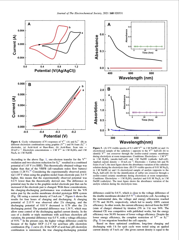
Figure 4. Cyclic voltammetry (CV) responses of V4+ (A) and S42− (B) in different electrolyte combinations using graphite (V4+) and Ni foam (S42−) electrodes. (a) Acid-Acid or Base-Base; (b) Acid-Base. Scan rate = 20 mV s−1. Electrolyte concentrations = 1 M V4+ in 1 M H2SO4 and 1 M Na2S4 in 1 M NaOH. According to the above Eqs. 1, one-electron transfer for the V4+ oxidation and two-electron reduction for S42− resulted in a combined potential of 1.45 V (vs SHE). This theoretically obtained voltage was higher than that of the VRFB (all-vanadium redox flow battery) system (1.26 V).41 Considering the experimentally observed poten- tial 1.05 V when using the graphite-nickel foam electrode pair, 0.4 V higher, this means that the experimentally observed potential was 0.4 V lower than the theoretically derived one. The difference in potential may be due to the graphite-nickel electrode pair that can be increased if the electrode pair is changed. With these considerations, the charging-discharging performance was evaluated for the V/S redox pair by the zeolite membrane divided prototype RFB system (Fig. 1B) using a current density of 5 mA cm−2. Figure 6 shows the results for four hours of charging and discharging. A charging potential of 2.15 V was observed after 2 h charging, and the discharging potential of 0.81 V decreased to 0.79 after the 2 h discharging period. The potential difference was 1.34 V, which may allow some control of the discharging applied current density. In the case of a double or triple membrane with acid-base electrolyte pH variation, the potential difference was 0.5 V, with a voltage efficiency of 91%.31 In the present case, the higher voltage difference could be because of the higher OCP (1.2V for acid-base pHs electrolyte combination (Fig. 2 curve d)). If the OCP of acid-base pH electrolyte combination is minimized, the true charging-discharging potential Figure 5. (A) UV-visible spectra of 0.1 mM V4+ in 1 M NaOH (a) and 1 h electrolyzed sample of the catholyte ( opposite to the V4+ half-ell) (b) to identify V4+ ion crossover through the zeolite-coated ceramic membrane during electrolysis at room temperature. Conditions: Electrolytes = 1 M V4+ in 1 M H2SO4 (anodic-half-cell) and 1 M NaOH (cathodic half-cell). Applied current density = 10 mA cm−2; Electrodes = Carbon felt and Ni foam (4 cm2); the inset figure shows the absorbance variation of the catholyte solution during the electrolysis time. (B) UV-visible spectra of 0.01 M Na2S4 in 1 M NaOH (a) and 1 h electrolyzed sample of anolyte (opposite to the Na2S4 half-cell) (b) for the identification of sulfur ion crossover through a zeolite-coated ceramic membrane during electrolysis at room temperature. Conditions: Electrolytes = 1 M H2SO4 (anolyte) and 0.01 M Na2S4 in 1 M NaOH (catholyte). The inset figure shows the absorbance variation of the anolyte solution during the electrolysis time. difference could be 0.6 V, which is close to the voltage difference of the double membrane-divided (0.5 V31) electrolytic cell. According to the instrumental data, the voltage and energy efficiencies reached 37.7% and 36.9%, respectively, which led to nearly 100% current efficiency. In other words, the current efficiency derived from the SOC (state of charge) obtained by titration (5% in 1 h) was 94%. The obtained CE was competitive with published works, but the energy efficiency was 36.9% because of lower voltage efficiency. Despite the lower energy efficiency, the complete restriction of V4+ or S42+ (Fig. 5) ion migration benefited the cell capacity. Based on these optimized conditions, long-time charging and discharging with 1h for each cycle were tested using an applied current density of 5 mA cm2 (the given current density is equal to the Journal of The Electrochemical Society, 2021 168 020531PDF Image | Acid-Base Electrolyte at Each Half-Cell with a Single Zeolite Membrane
PDF Search Title:
Acid-Base Electrolyte at Each Half-Cell with a Single Zeolite MembraneOriginal File Name Searched:
Electrochem-020531.pdfDIY PDF Search: Google It | Yahoo | Bing
CO2 Organic Rankine Cycle Experimenter Platform The supercritical CO2 phase change system is both a heat pump and organic rankine cycle which can be used for those purposes and as a supercritical extractor for advanced subcritical and supercritical extraction technology. Uses include producing nanoparticles, precious metal CO2 extraction, lithium battery recycling, and other applications... More Info
Heat Pumps CO2 ORC Heat Pump System Platform More Info
| CONTACT TEL: 608-238-6001 Email: greg@infinityturbine.com | RSS | AMP |