PDF Publication Title:
Text from PDF Page: 006
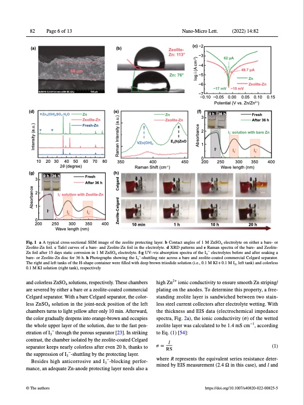
82 Page 6 of 13 Nano-Micro Lett. (2022) 14:82 (a) (b) 66 μm (c) −2 −3 −4 −5 −6 −17 mV −7 (d) (g) Zn (f) 0 h 3 2 1 0200 36 h Fresh After 36 h I3- solution with bare Zn I3- I3- SU8010 5.0 kV 9.4 mm x500 SE (UL) Zn4(OH)6SO4·H2O 100 μm −15 mV Zeolite- Zn: 113° Zn: 76° (e) Zn Zeolite-Zn 62 μA −0.10 −0.05 0.00 0.05 0.10 0.15 Potential (V vs. Zn/Zn2+) 49.7 μA Zn Zeolite-Zn 10 20 30 40 50 60 70 80 2θ (degree) 300 350 400 Zeolite-Zn Fresh-Zn VZn(OH)2 350 400 Raman Shift (cm-1) E2(h)ZnO I- 3 2 1 2000 0 h I- 36 h Fresh (h) After 36 h I3- solution with Zeolite-Zn I3- I3- 250 300 350 400 Wave Iength (nm) 10 min 1 h 10 h 20 h 450 250 Wave Iength (nm) Fig. 1 a A typical cross-sectional SEM image of the zeolite protecting layer. b Contact angles of 1 M ZnSO4 electrolyte on either a bare- or Zeolite-Zn foil. c Tafel curves of a bare- and Zeolite-Zn foil in the electrolyte. d XRD patterns and e Raman spectra of the bare- and Zeolite- Zn foil after 15 days static corrosion in 1 M ZnSO4 electrolyte. f‐g UV–vis absorption spectra of the I3− electrolytes before and after soaking a bare- or Zeolite-Zn disc for 36 h. h Photographs showing the I3−-shuttling rate across a bare and zeolite-coated commercial Celgard separator. The right and left tanks of the H-shape container were filled with deep brown triiodide solution (i.e., 0.1 M KI + 0.1 M I2, left tank) and colorless 0.1 M KI solution (right tank), respectively and colorless ZnSO4 solutions, respectively. These chambers are severed by either a bare or a zeolite-coated commercial Celgard separator. With a bare Celgard separator, the color- less ZnSO4 solution in the joint-neck position of the left chambers turns to light yellow after only 10 min. Afterward, the color gradually deepens into orange-brown and occupies the whole upper layer of the solution, due to the fast pen- etration of I3− through the porous separator [23]. In striking contrast, the chamber isolated by the zeolite-coated Celgard separator keeps nearly colorless after even 20 h, thanks to the suppression of I3−-shuttling by the protecting layer. Besides high anticorrosive and I3−-blocking perfor- mance, an adequate Zn-anode protecting layer needs also a © The authors high Zn2+ ionic conductivity to ensure smooth Zn striping/ plating on the anodes. To determine this property, a free- standing zeolite layer is sandwiched between two stain- less steel current collectors after electrolyte wetting. With the thickness and EIS data (electrochemical impedance spectra, Fig. 2a), the ionic conductivity (σ) of the wetted zeolite layer was calculated to be 1.4 mS cm−1, according to Eq. (1) [54]: l mined by EIS measurement (2.4 Ω in this case), and l and https://doi.org/10.1007/s40820-022-00825-5 𝜎=RS (1) where R represents the equivalent series resistance deter- Absorbance Intensity (a.u.) Zeolite-Celgard Celgard Raman Intensity (a.u.) Absorbance Iog i (A cm-2)PDF Image | Boosting Zn Battery by Coating a Zeolite‐Based Cation‐Exchange
PDF Search Title:
Boosting Zn Battery by Coating a Zeolite‐Based Cation‐ExchangeOriginal File Name Searched:
Shang2022_ZnI-Battery.pdfDIY PDF Search: Google It | Yahoo | Bing
CO2 Organic Rankine Cycle Experimenter Platform The supercritical CO2 phase change system is both a heat pump and organic rankine cycle which can be used for those purposes and as a supercritical extractor for advanced subcritical and supercritical extraction technology. Uses include producing nanoparticles, precious metal CO2 extraction, lithium battery recycling, and other applications... More Info
Heat Pumps CO2 ORC Heat Pump System Platform More Info
| CONTACT TEL: 608-238-6001 Email: greg@infinityturbine.com | RSS | AMP |