PDF Publication Title:
Text from PDF Page: 004
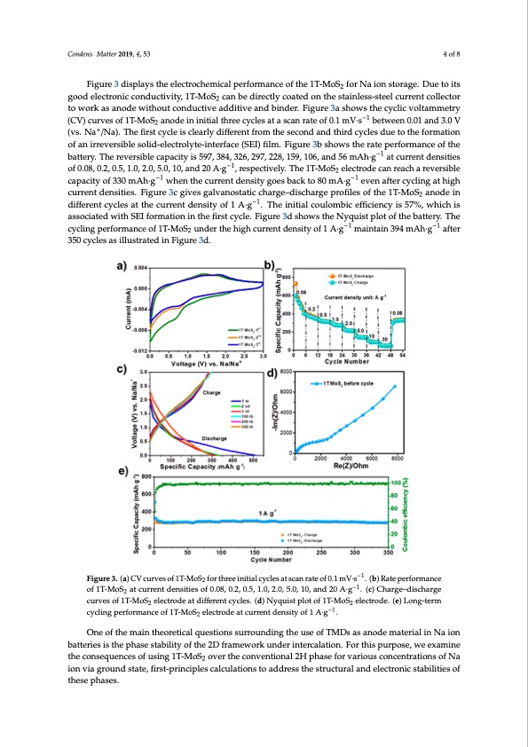
Condens. Matter 2019, 4, 53 4 of 8 Figure 3 displays the electrochemical performance of the 1T-MoS2 for Na ion storage. Due to its good electronic conductivity, 1T-MoS2 can be directly coated on the stainless-steel current collector to work as anode without conductive additive and binder. Figure 3a shows the cyclic voltammetry (CV) curves of 1T-MoS2 anode in initial three cycles at a scan rate of 0.1 mV·s−1 between 0.01 and 3.0 V (vs. Na+/Na). The first cycle is clearly different from the second and third cycles due to the formation of an irreversible solid-electrolyte-interface (SEI) film. Figure 3b shows the rate performance of the battery. The reversible capacity is 597, 384, 326, 297, 228, 159, 106, and 56 mAh·g−1 at current densities of 0.08, 0.2, 0.5, 1.0, 2.0, 5.0, 10, and 20 A·g−1, respectively. The 1T-MoS2 electrode can reach a reversible capacity of 330 mAh·g−1 when the current density goes back to 80 mA·g−1 even after cycling at high current densities. Figure 3c gives galvanostatic charge–discharge profiles of the 1T-MoS2 anode in different cycles at the current density of 1 A·g−1. The initial coulombic efficiency is 57%, which is associated with SEI formation in the first cycle. Figure 3d shows the Nyquist plot of the battery. The cycling performance of 1T-MoS2 under the high current density of 1 A·g−1 maintain 394 mAh·g−1 after 350 cycles as illustrated in Figure 3d. Condens. Matter 2019, 4, x FOR PEER REVIEW 5 of 10 Figure 3. (a) CV curves of 1T-MoS2 for three initial cycles at scan rate o−f1 0.1 mV∙s−1. (b) Rate Figure 3. (a) CV curves of 1T-MoS2 for three initial cycles at scan rate of 0.1 mV·s . (b) Rate performance −1 −1 performance of 1T-MoS2 at current densities of 0.08, 0.2, 0.5, 1.0, 2.0, 5.0, 10, and 20 A∙g . of 1T-MoS2 at current densities of 0.08, 0.2, 0.5, 1.0, 2.0, 5.0, 10, and 20 A·g . (c) Charge–discharge (cu)rCvehsaorfg1eT–-dMisocShaerlgecetrcoudrevaetsdoifffe1reTn-tMcyocSl2ese.l(edc)trNoydqeuiast pdlioffteorfe1nTt-McyocSlese.le(cdtr)oNdey.q(eu)isLtonpglo-teromf 22 −1 1cTyc-MlinogSp2eerfloercmtraondce.o(fe1)T-LMoonSg-teelercmtrocdyecalitncgurrpeenrtfdoermnsaitnycoef 1ofA·1gT-M. oS2 electrode at current density of 1 A∙g−1. 2 One of the main theoretical questions surrounding the use of TMDs as anode material in Na ion batteries is the phase stability of the 2D framework under intercalation. For this purpose, we examine One of the main theoretical questions surrounding the use of TMDs as anode material in Na ion theconsequencesofusing1T-MoS overtheconventional2HphaseforvariousconcentrationsofNa batteries is the phase stability of2 the 2D framework under intercalation. For this purpose, we ion via ground state, first-principles calculations to address the structural and electronic stabilities of examine the consequences of using 1T-MoS2 over the conventional 2H phase for various these phases. concentrations of Na ion via ground state, first-principles calculations to address the structural and electronic stabilities of these phases. For specific capacities over the range 0–146 mAh∙g−1, we considered a 4 × 4 supercell of A-A stacked pristine 1T- and 2H-MoS2 structures, as shown in Figure 4b’,b respectively, where the Mo atom (purple sphere) in the 2H structure is trigonal-prismatically coordinated with S (yellow sphere), while in the 1T phase it is octahedrally coordinated. Under intercalation, the structures arePDF Image | Understanding Phase Stability of Metallic 1T-MoS2 Anodes for Sodium-Ion Batteries
PDF Search Title:
Understanding Phase Stability of Metallic 1T-MoS2 Anodes for Sodium-Ion BatteriesOriginal File Name Searched:
condensedmatter-04-00053.pdfDIY PDF Search: Google It | Yahoo | Bing
Sulfur Deposition on Carbon Nanofibers using Supercritical CO2 Sulfur Deposition on Carbon Nanofibers using Supercritical CO2. Gamma sulfur also known as mother of pearl sulfur and nacreous sulfur... More Info
CO2 Organic Rankine Cycle Experimenter Platform The supercritical CO2 phase change system is both a heat pump and organic rankine cycle which can be used for those purposes and as a supercritical extractor for advanced subcritical and supercritical extraction technology. Uses include producing nanoparticles, precious metal CO2 extraction, lithium battery recycling, and other applications... More Info
| CONTACT TEL: 608-238-6001 Email: greg@infinityturbine.com | RSS | AMP |