PDF Publication Title:
Text from PDF Page: 085
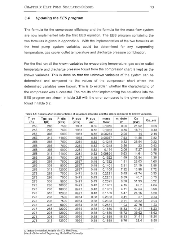
CHAPTER 3: HEAT PUMP SIMULATIONMoDEL 73 3.4 Updating the EES program The formula for the compressor efficiency and the formula for the mass flow system are now implemented into the first EES equation. The program containing the two formulas is given in Appendix A. With the implementation of the two formulas all the heat pump system variables could be determined for any evaporating temperature, gas cooler outlet temperature and discharge pressure combination. For the first run all the known variables for evaporating temperature, gas cooler outlet temperature and discharge pressure found from the compressor chart is kept as the known variables. This is done so that the unknown variables of the system can be determined and compared to the values of the compressor chart where the determined variables were known. This is to establish whether the characterizing of the compressor was successful. The results after implementing the equations into the EES program are shown in table 3.5 with the error compared to the given variables found in table 3.2. Table 3.5: Results after implementation of equations into EES and the errors compared to known variables. T_ev (K) 253 253 253 Tgc_ou P dis t(K) (kPa) 288 7500 298 7500 308 9000 313 11000 288 7500 298 7500 308 9000 313 11000 288 7500 298 7500 308 9000 313 12000 P_suc • P_suc_ mass m_dote Qe flow rr (kW) • 0.1016 • 0.09254 0.08037 0.1248 0.1248 0.114 0.59 18.71 I 0.48. 2~=~t 2.19 7. 11.86 7.82 253 258 258 258 258 263 263 263 263 273 273 I 298 ! . I • • ! ! 0.09894 I 0.1522 0.1522 0.1401 0.1105 0.2231 0.2231 0.2095 0.1961 0.1961 0.1589 0.2683 0.2683 0.2551 0.1889 0.1889 0.1889 0.1889 0.32 0.56 2.06 0.63 1.49 1.81 2.91 7.92 0.45 0.89 0.38 4.15 • 4.11 5.47 0.41 0.11 1.03 18.33 18.72 18.33 6.76 I .94 0.22 23 0.43 17.27 1.88 14N 0.76 32.84 1.38 28.03 1.65 21.19 2.80 16.98 7.72 47.74 0.33 4¥s-H73 • 288 7500 7500 ! 308 9000 288 • 10000 298 ! 10000 313 12000 288 7500 298 7500 308 9000 288 12000 298 12000 308 12000 278 I 313 12000 • • 273 273 273 273 I 278 278 278 I 278 278 278 • ! 31. 42.7 • 37.54 • 24.15 I 57 48.5~ .22 4.04 3. 5.29 • 0.53 • 0.04 I 1.23 ! A Techno-Economical Analysis of a CO2 Heat Pump. School ofMechanical Engineering, North-West University (kPa) • 1961 i 1961 1961 • 1961 2281 2281 2281 2281 2637 2637 2637 2637 3471 3471 3471 3471 3471 3471 3954 I 3954 3954 """14 3954 3954 3954 err 0.56 0.56 0.56 0.56 0.52 0.52 0.52 0.52 0.49 0.49 0.49 0.49 0.43 I 0.43 0.43 0.43 0.43 0.43 0.38 0.38 0.38 0.38 0.38 0.38 u.38 I Qe_err 0.1016 0.00 21.92 0.09 37.76 41.21 18.23 36.62 31.41 18. 28.4 6.58 1~To1PDF Image | CO2 HEAT PUMP Analysis
PDF Search Title:
CO2 HEAT PUMP AnalysisOriginal File Name Searched:
co2-heat-pump-techno-analysis.pdfDIY PDF Search: Google It | Yahoo | Bing
CO2 Organic Rankine Cycle Experimenter Platform The supercritical CO2 phase change system is both a heat pump and organic rankine cycle which can be used for those purposes and as a supercritical extractor for advanced subcritical and supercritical extraction technology. Uses include producing nanoparticles, precious metal CO2 extraction, lithium battery recycling, and other applications... More Info
Heat Pumps CO2 ORC Heat Pump System Platform More Info
| CONTACT TEL: 608-238-6001 Email: greg@infinityturbine.com | RSS | AMP |