PDF Publication Title:
Text from PDF Page: 004
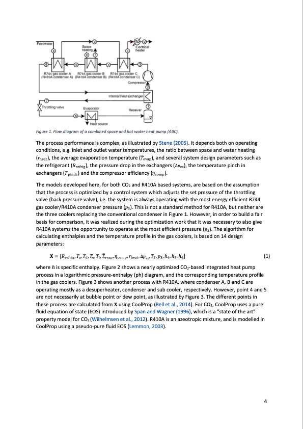
Figure 1. Flow diagram of a combined space and hot water heat pump (ABC). The process performance is complex, as illustrated by Stene (2005). It depends both on operating (𝑟𝑟 ), the average evaporation temperature (𝑇𝑇� ), and several system design parameters such as heat evap conditions, e.g. inlet and outlet water temperatures, the ratio between space and water heating the refrigerant (𝑅𝑅refrig), the pressure drop in the exchangers (Δ𝑝𝑝ex), the temperature pinch in exchangers (𝑇𝑇pinch) and the compressor efficiency (𝜂𝜂comp). The models developed here, for both CO2 and R410A based systems, are based on the assumption that the process is optimized by a control system which adjusts the set pressure of the throttling gas cooler/R410A condenser pressure (𝑝𝑝 ). This is not a standard method for R410A, but neither are 3 valve (back pressure valve), i.e. the system is always operating with the most energy efficient R744 the three coolers replacing the conventional condenser in Figure 1. However, in order to build a fair R410A systems the opportuni�ty to operate at the most efficient pressure (𝑝𝑝 ). The algorithm for basis for comparison, it was realized during the optimization work that it was necessary to also give calculating enthalpies and the temperature profile in the gas coolers, is based on 14 design parameters: 𝐗𝐗 = [𝑅𝑅 , 𝑇𝑇 , 𝑇𝑇 , 𝑇𝑇 , 𝑇𝑇 , 𝑇𝑇 , 𝜂𝜂 , 𝑟𝑟 , Δ𝑝𝑝 , 𝑇𝑇 , 𝑝𝑝 , h , h , h ] (1) refrig a d e f evap comp heat ex 2 3 4 5 6 where h is specific enthalpy. Figure 2 shows a nearly optimized CO2-based integrated heat pump process in a logarithmic pressure-enthalpy (ph) diagram, and the corresponding temperature profile in the gas coolers. Figure 3 shows another process with R410A, where condenser A, B and C are operating mostly as a desuperheater, condenser and sub cooler, respectively. However, point 4 and 5 are not necessarily at bubble point or dew point, as illustrated by Figure 3. The different points in these process are calculated from 𝐗𝐗 using CoolProp (Bell et al., 2014). For CO2, CoolProp uses a pure fluid equation of state (EOS) introduced by Span and Wagner (1996), which is a “state of the art” property model for CO2 (Wilhelmsen et al., 2012). R410A is an azeotropic mixture, and is modelled in CoolProp using a pseudo-pure fluid EOS (Lemmon, 2003). 3 4PDF Image | CO2 Heat Pump Performance
PDF Search Title:
CO2 Heat Pump PerformanceOriginal File Name Searched:
co2-heat-pump-comparative-study.pdfDIY PDF Search: Google It | Yahoo | Bing
CO2 Organic Rankine Cycle Experimenter Platform The supercritical CO2 phase change system is both a heat pump and organic rankine cycle which can be used for those purposes and as a supercritical extractor for advanced subcritical and supercritical extraction technology. Uses include producing nanoparticles, precious metal CO2 extraction, lithium battery recycling, and other applications... More Info
Heat Pumps CO2 ORC Heat Pump System Platform More Info
| CONTACT TEL: 608-238-6001 Email: greg@infinityturbine.com | RSS | AMP |