PDF Publication Title:
Text from PDF Page: 005
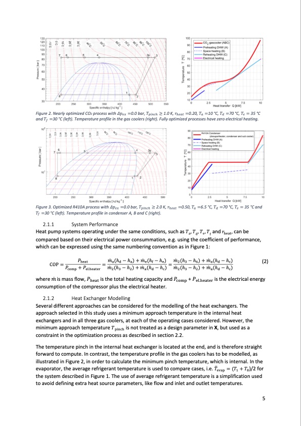
Figure 2. Nearly optimized CO2 process with 𝛥𝛥𝑝𝑝𝑒𝑒𝑒𝑒 =0.0 bar, 𝑇𝑇𝑝𝑝𝑝𝑝𝑝𝑝𝑝𝑝h ≥ 1.0 K, 𝑟𝑟h𝑒𝑒𝑒𝑒𝑒𝑒 =0.20, 𝑇𝑇𝑒𝑒 =10 °C, 𝑇𝑇𝑑𝑑 =70 °C, 𝑇𝑇𝑒𝑒 = 35 °C and 𝑇𝑇𝑓𝑓 =30 °C (left). Temperature profile in the gas coolers (right). Fully optimized processes have zero electrical heating. Figure 3. Optimized R410A process with 𝛥𝛥𝑝𝑝𝑒𝑒𝑒𝑒 =0.0 bar, 𝑇𝑇𝑝𝑝𝑝𝑝𝑝𝑝𝑝𝑝h ≥ 2.0 K, 𝑟𝑟h𝑒𝑒𝑒𝑒𝑒𝑒 =0.50, 𝑇𝑇𝑒𝑒 =6.5 °C, 𝑇𝑇𝑑𝑑 =70 °C, 𝑇𝑇𝑒𝑒 = 35 °C and 𝑇𝑇𝑓𝑓 =30 °C (left). Temperature profile in condenser A, B and C (right). 2.1.1 System Performance Heat pump systems operating under the same conditions, such as 𝑇𝑇 , 𝑇𝑇 , 𝑇𝑇 , 𝑇𝑇 and 𝑟𝑟 , can be adef heat compared based on their electrical power consummation, e.g. using the coefficient of performance, which can be expressed using the same numbering convention as in Figure 1: COP= 𝑃𝑃 =𝑚𝑚̇ (h −h)+𝑚𝑚̇ (h−h)=𝑚𝑚̇ (h −h)+𝑚𝑚̇ (h −h) heat adaefe236adc (2) 𝑃𝑃 +𝑃𝑃 𝑚𝑚̇ (h −h)+𝑚𝑚̇ (h −h) 𝑚𝑚̇ (h −h)+𝑚𝑚̇ (h −h) comp el.heater 2 3 2 a d c 2 3 2 a d c where 𝑚𝑚̇ is mass flow, 𝑃𝑃heat is the total heating capacity and 𝑃𝑃comp + 𝑃𝑃el.heater is the electrical energy consumption of the compressor plus the electrical heater. 2.1.2 Heat Exchanger Modelling Several different approaches can be considered for the modelling of the heat exchangers. The approach selected in this study uses a minimum approach temperature in the internal heat minimum approach temperature 𝑇𝑇 is not treated as a design parameter in X, but used as a pinch exchangers and in all three gas coolers, at each of the operating cases considered. However, the constraint in the optimization process as described in section 2.2. The temperature pinch in the internal heat exchanger is located at the end, and is therefore straight forward to compute. In contrast, the temperature profile in the gas coolers has�to be modelled, as evaporator, the average refrigerant temperature is used to compare cases, i.e. 𝑇𝑇 = (𝑇𝑇 + 𝑇𝑇 )/2 for evap 1 8 illustrated in Figure 2, in order to calculate the minimum pinch temperature, which is internal. In the the system described in Figure 1. The use of average refrigerant temperature is a simplification used to avoid defining extra heat source parameters, like flow and inlet and outlet temperatures. 5PDF Image | CO2 Heat Pump Performance
PDF Search Title:
CO2 Heat Pump PerformanceOriginal File Name Searched:
co2-heat-pump-comparative-study.pdfDIY PDF Search: Google It | Yahoo | Bing
CO2 Organic Rankine Cycle Experimenter Platform The supercritical CO2 phase change system is both a heat pump and organic rankine cycle which can be used for those purposes and as a supercritical extractor for advanced subcritical and supercritical extraction technology. Uses include producing nanoparticles, precious metal CO2 extraction, lithium battery recycling, and other applications... More Info
Heat Pumps CO2 ORC Heat Pump System Platform More Info
| CONTACT TEL: 608-238-6001 Email: greg@infinityturbine.com | RSS | AMP |