PDF Publication Title:
Text from PDF Page: 006
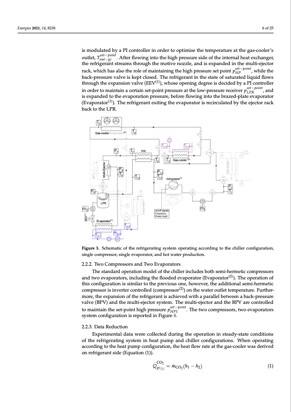
Energies 2021, 14, 8238 6 of 25 is modulated by a PI controller in order to optimise the temperature at the gas-cooler’s outlet, Tset−point. After flowing into the high pressure side of the internal heat exchanger, out−gc the refrigerant streams through the motive nozzle, and is expanded in the multi-ejector rack, which has also the role of maintaining the high pressure set point pset−point, while the HP back-pressure valve is kept closed. The refrigerant in the state of saturated liquid flows through the expansion valve (EEV(1)), whose opening degree is decided by a PI controller in order to maintain a certain set-point pressure at the low-pressure receiver pset−point, and LPR is expanded to the evaporation pressure, before flowing into the brazed-plate evaporator (Evaporator(1)). The refrigerant exiting the evaporator is recirculated by the ejector rack back to the LPR. Figure 3. Schematic of the refrigerating system operating according to the chiller configuration, single compressor, single evaporator, and hot water production. 2.2.2. Two Compressors and Two Evaporators The standard operation model of the chiller includes both semi-hermetic compressors and two evaporators, including the flooded evaporator (Evaporator(2)). The operation of this configuration is similar to the previous one, however, the additional semi-hermetic compressor is inverter controlled (compressor(2)) on the water outlet temperature. Further- more, the expansion of the refrigerant is achieved with a parallel between a back-pressure valve (BPV) and the multi-ejector system. The multi-ejector and the BPV are controlled to maintain the set-point high pressure pset−point. The two compressors, two evaporators HP1 system configuration is reported in Figure 4. 2.2.3. Data Reduction Experimental data were collected during the operation in steady-state conditions of the refrigerating system in heat pump and chiller configurations. When operating according to the heat pump configuration, the heat flow rate at the gas-cooler was derived on refrigerant side (Equation (1)). Q.CO2 =m. (h−h) (1) gc(1) CO2 1 2PDF Image | Dynamic Modelling and Validation of an Air-to-Water Reversible R744
PDF Search Title:
Dynamic Modelling and Validation of an Air-to-Water Reversible R744Original File Name Searched:
Artuso2021dma_publisert.pdfDIY PDF Search: Google It | Yahoo | Bing
CO2 Organic Rankine Cycle Experimenter Platform The supercritical CO2 phase change system is both a heat pump and organic rankine cycle which can be used for those purposes and as a supercritical extractor for advanced subcritical and supercritical extraction technology. Uses include producing nanoparticles, precious metal CO2 extraction, lithium battery recycling, and other applications... More Info
Heat Pumps CO2 ORC Heat Pump System Platform More Info
| CONTACT TEL: 608-238-6001 Email: greg@infinityturbine.com | RSS | AMP |