PDF Publication Title:
Text from PDF Page: 004
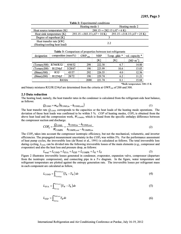
and binary mixtures R32/R1234yf are determined from the criteria at GWP100 of 200 and 300. 2.3 Data reduction The heating load, namely, the heat transfer rates in the condenser is calculated from the refrigerant-side heat balance, as follows: QCOND mref hCOND,in hCOND,out (1) The heat transfer rate QCOND corresponds to the capacities or the heat loads of the heating mode operations. The deviation of those heat loads was confirmed to be within 5 %. COP of heating modes, COPh is obtained from the above heat load and the compression work, WCOMPR, which is found from the specific enthalpy difference between the compressor suction and discharge. COP QCOND hCOND,in hCOND,out (2) Ltotal LCOND LEVA LEXP LCOMPR LH LP (3) Figure 2 illustrates irreversible losses generated in condenser, evaporator, expansion valve, compressor (departure from the isentropic compression), and connecting pipe in a T-s diagram. In the figure, water temperature and refrigerant temperature are plotted against the entropy generation rate. The irreversible losses per refrigerant mass in each component are calculated as follow, L sCOND,outT T ds (4) COND s R W CO N D ,in L sEVA,outT T ds (5) EVA s W R EV A ,in LEXP ssEXP,outTRds (6) E X P ,in h WCOMPR hCOMPR,out hCOMPR,in The COPh takes into account the compressor isentropic efficiency, but not the mechanical, volumetric, and inverter efficiencies. The propagated measurement uncertainty in the COPh was within 5%. For the performance assessment of heat pump cycles, the irreversible loss (de’Rossi et al., 1991) is calculated as follows. The total irreversible loss during cycling, Ltotal, can be divided into the following irreversible losses of the main elements (e.g., compressor and evaporator) and also the heat loss and pressure drop, as follows: 2205, Page 3 Heat source temperature [K] Heat sink temperature [K] Degree of superheat [K] Heat transfer rate [kW] (Heating/cooling heat load) Table 2: Experimental conditions Heating mode 1 Heating mode 2 288.15→ 282.15 (ΔT = 6 K) 293.15→303.15 (ΔT = 10 K) 293.15→318.15 (ΔT = 25 K) 3 2.2 Table 3: Comparison of properties between test refrigerants designation composition (mass%) GWP100 NBP [K] (Ternary300) R744/R32/ 4/44/52 298 222.30 Temp. glide * [K] vol. capacity * [MJ・m-3] 14.00 13.03 12.56 11.21 0.1 *Bulk temperature 308.15 K (Ternary200) R1234yf (Binary300) R32/ (Binary200) R1234yf R410A 6.7 10.6 4.0 6.2 5/28/67 190 223.99 43/57 292 226.55 28/72 190 229.74 2088 221.74 15.04 International Refrigeration and Air Conditioning Conference at Purdue, July 16-19, 2012PDF Image | Experimental Assessment on Performance of a Heat Pump Cycle

PDF Search Title:
Experimental Assessment on Performance of a Heat Pump CycleOriginal File Name Searched:
heat-pump-cycle-analysis.pdfDIY PDF Search: Google It | Yahoo | Bing
CO2 Organic Rankine Cycle Experimenter Platform The supercritical CO2 phase change system is both a heat pump and organic rankine cycle which can be used for those purposes and as a supercritical extractor for advanced subcritical and supercritical extraction technology. Uses include producing nanoparticles, precious metal CO2 extraction, lithium battery recycling, and other applications... More Info
Heat Pumps CO2 ORC Heat Pump System Platform More Info
| CONTACT TEL: 608-238-6001 Email: greg@infinityturbine.com | RSS | AMP |