PDF Publication Title:
Text from PDF Page: 031
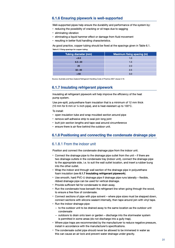
6.1.6 Ensuring pipework is well-supported Well-supported pipes help ensure the durability and performance of the system by: • reducing the possibility of cracking or oil traps due to sagging • eliminating vibration • eliminating a liquid hammer effect or damage from fluid movement • resulting in better fluid handling characteristics. As good practice, copper tubing should be fixed at the spacings given in Table 6.1. Table 6.1 Fixing spacings for copper tubing Source: Australia and New Zealand Refrigerant Handling Code of Practice 2007 clause 5.18. 6.1.7 Insulating refrigerant pipework Insulating all refrigerant pipework will help improve the efficiency of the heat pump system. Use pre-split, polyurethane foam insulation that is a minimum of 12 mm thick (10 mm for 6 mm or 1⁄4 inch pipe), and is heat-resistant up to 100°C. To install: • open insulation tube and wrap moulded section around pipe • remove self-adhesive strip to seal-join long joint • butt-join section lengths and tape seal around circumference • ensure there is air flow behind the outdoor unit. 6.1.8 Positioning and connecting the condensate drainage pipe 6.1.8.1 From the indoor unit Position and connect the condensate drainage pipe from the indoor unit. • Connect the drainage pipe to the drainage pipe outlet from the unit – if there are two drainage outlets in the condensate tray (indoor unit), connect the drainage pipe to the appropriate side, i.e. to suit the wall outlet location, and insert a rubber bung into the other outlet. • Wrap the indoor and through wall section of the drainage pipe in polyurethane foam insulation (see 6.1.7 Insulating refrigerant pipework). • Use smooth, hard PVC-U drainage pipe if drainage pipe runs laterally – flexible, ribbed drainage pipe can be used for vertical drainage. • Provide sufficient fall for condensate to drain away. • Run the condensate hose beneath the refrigerant line when going through the wood, to ensure a free flow of condensate. • Connect sections of pipe with pipe solvent – where pipe sizes must be stepped down, connect sections with silicone sealant internally, then tape around join with vinyl tape. • Run the indoor drainage pipe: – to the outdoor unit to be drained away to the same location as the outdoor unit condensate – outdoors to drain onto lawn or garden – discharge into the stormwater system is permitted in some areas (do not discharge into a gully trap). • Where pipe traps are recommended by the manufacturer to reduce negative pressure, install in accordance with the manufacturer’s specifications. • The condensate outlet pipe should never be allowed to be immersed in water as this can cause an air lock and prevent water drainage under gravity. Tubing diameter (mm) Maximum fixing spacing (m) < 6.5 1.0 6.5–20 1.5 25 2.0 32–40 2.5 >50 3.0 31PDF Image | Heat pump installation Good Practice Guide
PDF Search Title:
Heat pump installation Good Practice GuideOriginal File Name Searched:
Good_practice_heat_pump_installation.pdfDIY PDF Search: Google It | Yahoo | Bing
CO2 Organic Rankine Cycle Experimenter Platform The supercritical CO2 phase change system is both a heat pump and organic rankine cycle which can be used for those purposes and as a supercritical extractor for advanced subcritical and supercritical extraction technology. Uses include producing nanoparticles, precious metal CO2 extraction, lithium battery recycling, and other applications... More Info
Heat Pumps CO2 ORC Heat Pump System Platform More Info
| CONTACT TEL: 608-238-6001 Email: greg@infinityturbine.com | RSS | AMP |