PDF Publication Title:
Text from PDF Page: 010
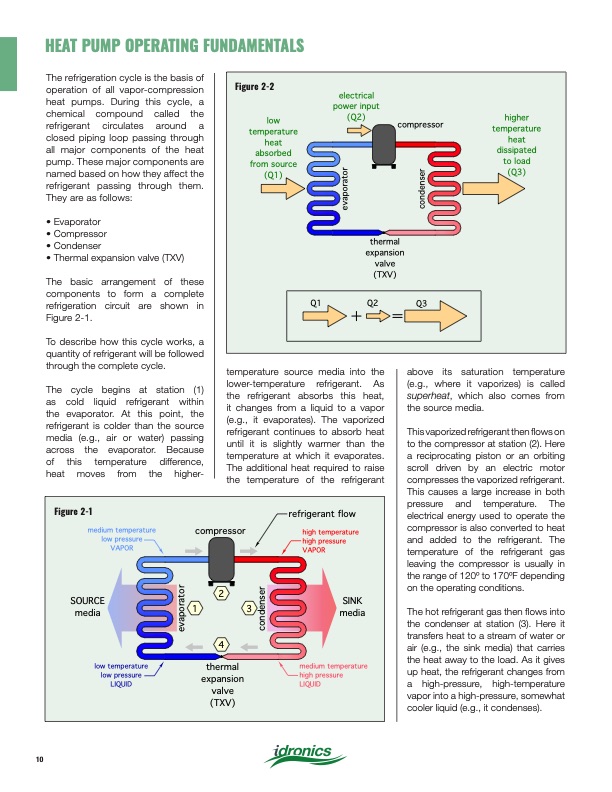
The refrigeration cycle is the basis of operation of all vapor-compression heat pumps. During this cycle, a chemical compound called the refrigerant circulates around a closed piping loop passing through all major components of the heat pump. These major components are named based on how they affect the refrigerant passing through them. They are as follows: • Evaporator • Compressor • Condenser • Thermal expansion valve (TXV) The basic arrangement of these components to form a complete refrigeration circuit are shown in Figure 2-1. To describe how this cycle works, a quantity of refrigerant will be followed through the complete cycle. The cycle begins at station (1) as cold liquid refrigerant within the evaporator. At this point, the refrigerant is colder than the source media (e.g., air or water) passing across the evaporator. Because of this temperature difference, heat moves from the higher- temperature source media into the lower-temperature refrigerant. As the refrigerant absorbs this heat, it changes from a liquid to a vapor (e.g., it evaporates). The vaporized refrigerant continues to absorb heat until it is slightly warmer than the temperature at which it evaporates. The additional heat required to raise the temperature of the refrigerant above its saturation temperature (e.g., where it vaporizes) is called superheat, which also comes from the source media. This vaporized refrigerant then flows on to the compressor at station (2). Here a reciprocating piston or an orbiting scroll driven by an electric motor compresses the vaporized refrigerant. This causes a large increase in both pressure and temperature. The electrical energy used to operate the compressor is also converted to heat and added to the refrigerant. The temperature of the refrigerant gas leaving the compressor is usually in the range of 120o to 170oF depending on the operating conditions. The hot refrigerant gas then flows into the condenser at station (3). Here it transfers heat to a stream of water or air (e.g., the sink media) that carries the heat away to the load. As it gives up heat, the refrigerant changes from a high-pressure, high-temperature vapor into a high-pressure, somewhat cooler liquid (e.g., it condenses). Figure 2-2 low temperature heat absorbed from source (Q1) electrical power input (Q2) compressor higher temperature heat dissipated to load (Q3) thermal expansion valve (TXV) Q1 Q2 Q3 Figure 2-1 medium temperature low pressure VAPOR SOURCE media low temperature low pressure LIQUID compressor refrigerant flow high temperature high pressure VAPOR SINK media medium temperature high pressure LIQUID 1 2 4 thermal expansion valve (TXV) 3 HEAT PUMP OPERATING FUNDAMENTALS 10 evaporator condenser evaporator condenserPDF Image | Heat Pump Systems 2020
PDF Search Title:
Heat Pump Systems 2020Original File Name Searched:
idronics_27_na.pdfDIY PDF Search: Google It | Yahoo | Bing
CO2 Organic Rankine Cycle Experimenter Platform The supercritical CO2 phase change system is both a heat pump and organic rankine cycle which can be used for those purposes and as a supercritical extractor for advanced subcritical and supercritical extraction technology. Uses include producing nanoparticles, precious metal CO2 extraction, lithium battery recycling, and other applications... More Info
Heat Pumps CO2 ORC Heat Pump System Platform More Info
| CONTACT TEL: 608-238-6001 Email: greg@infinityturbine.com | RSS | AMP |