PDF Publication Title:
Text from PDF Page: 011
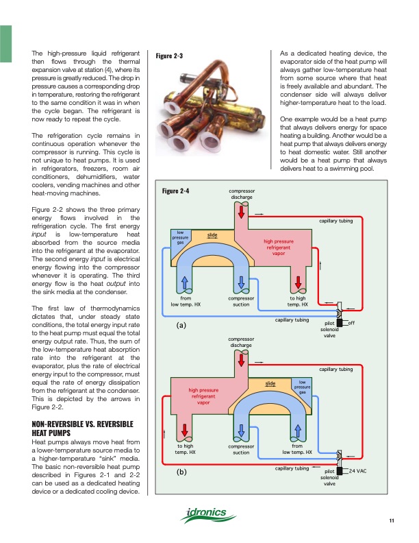
Figure 2-4 compressor! discharge capillary tubing low! pressure! gas from! low temp. HX slide high pressure refrigerant! vapor to high! temp. HX compressor! suction compressor! discharge slide capillary tubing valve capillary tubing valve capillary tubing low! pressure! gas from! low temp. HX (a) high pressure refrigerant! vapor pilot! off solenoid! to high! temp. HX (b) compressor! suction pilot! 24 VAC solenoid! The high-pressure liquid refrigerant then flows through the thermal expansion valve at station (4), where its pressure is greatly reduced. The drop in pressure causes a corresponding drop in temperature, restoring the refrigerant to the same condition it was in when the cycle began. The refrigerant is now ready to repeat the cycle. The refrigeration cycle remains in continuous operation whenever the compressor is running. This cycle is not unique to heat pumps. It is used in refrigerators, freezers, room air conditioners, dehumidifiers, water coolers, vending machines and other heat-moving machines. Figure 2-2 shows the three primary energy flows involved in the refrigeration cycle. The first energy input is low-temperature heat absorbed from the source media into the refrigerant at the evaporator. The second energy input is electrical energy flowing into the compressor whenever it is operating. The third energy flow is the heat output into the sink media at the condenser. The first law of thermodynamics dictates that, under steady state conditions, the total energy input rate to the heat pump must equal the total energy output rate. Thus, the sum of the low-temperature heat absorption rate into the refrigerant at the evaporator, plus the rate of electrical energy input to the compressor, must equal the rate of energy dissipation from the refrigerant at the condenser. This is depicted by the arrows in Figure 2-2. NON-REVERSIBLE VS. REVERSIBLE HEAT PUMPS Heat pumps always move heat from a lower-temperature source media to a higher-temperature “sink” media. The basic non-reversible heat pump described in Figures 2-1 and 2-2 can be used as a dedicated heating device or a dedicated cooling device. Figure 2-3 As a dedicated heating device, the evaporator side of the heat pump will always gather low-temperature heat from some source where that heat is freely available and abundant. The condenser side will always deliver higher-temperature heat to the load. One example would be a heat pump that always delivers energy for space heating a building. Another would be a heat pump that always delivers energy to heat domestic water. Still another would be a heat pump that always delivers heat to a swimming pool. 11PDF Image | Heat Pump Systems 2020
PDF Search Title:
Heat Pump Systems 2020Original File Name Searched:
idronics_27_na.pdfDIY PDF Search: Google It | Yahoo | Bing
CO2 Organic Rankine Cycle Experimenter Platform The supercritical CO2 phase change system is both a heat pump and organic rankine cycle which can be used for those purposes and as a supercritical extractor for advanced subcritical and supercritical extraction technology. Uses include producing nanoparticles, precious metal CO2 extraction, lithium battery recycling, and other applications... More Info
Heat Pumps CO2 ORC Heat Pump System Platform More Info
| CONTACT TEL: 608-238-6001 Email: greg@infinityturbine.com | RSS | AMP |