PDF Publication Title:
Text from PDF Page: 055
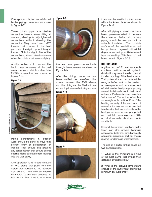
One approach is to use reinforced flexible piping connectors, as shown in Figure 7-7. These 1-inch pipe size flexible connectors have a swivel fitting at one end, allowing for fully tightened connections without stressing the connector. They have 1-inch MPT threads that connect to the heat pump and the rigid copper tubing at the wall. Note the slight offset of the connections, which minimizes stress when the outdoor unit moves slightly. Another option is to connect the heat pump to piping at the wall using corrugated stainless steel tube (CSST) assemblies, as shown in Figure 7-8. Figure 7-8 Figure 7-9 foam can be neatly trimmed away with a hacksaw blade, as shown in Figure 7-10. After all piping connections have been pressure-tested to ensure there are no leaks, all outdoor piping should be wrapped with a suitable insulation. The outside surface of the insulation should be protected against ultraviolet degradation using a UV-resistant tape or coating. This has not yet been done in Figure 7-11. BUFFER TANKS Anytime an on/off heat source is combined with a zoned hydronic distribution system, there is potential for short cycling of that heat source. That potential can be reduced by using a buffer tank in the system. An example would be a 4-ton on/ off air-to-water heat pump supplying several individually controlled panel radiators. Each radiator represents a “micro-zone.” The output of such a zone might only be 5 to 10% of the heating capacity of the heat pump. If several micro-zones are connected to a header that leads directly to the heat pump, even a heat pump that can modulate down to perhaps 30% of rated capacity, short cycling is very likely. Beyond this primary function, buffer tanks can also provide hydraulic separation between simultaneously operating circulators and an energy reserve for domestic water heating. The size of a buffer tank is based on two considerations: 1. What is the minimum run time of the heat pump that avoids their definition of “short cycle?” 2. What is the allowed temperature change of the buffer tank during the minimum on-cycle time? Courtesy of Enertech Global Piping penetrations in exterior walls should be done in ways that prevent entry of precipitation or insects. They should also prevent any condensation that occurs during cooling mode operation from leaking into the wall cavity. One approach is to create sleeves of PVC piping that pass from the inside wall surface to the outside wall surface. The sleeves should be sealed to the wall surfaces at both ends. The pipes to and from Figure 7-11 the heat pump pass concentrically through these sleeves, as shown in Figure 7-9. After the piping connection has been verified as leak-free, the space between the PVC sleeve and the piping can be filled with an expanding foam sealant. Any excess Figure 7-10 55PDF Image | Heat Pump Systems 2020
PDF Search Title:
Heat Pump Systems 2020Original File Name Searched:
idronics_27_na.pdfDIY PDF Search: Google It | Yahoo | Bing
CO2 Organic Rankine Cycle Experimenter Platform The supercritical CO2 phase change system is both a heat pump and organic rankine cycle which can be used for those purposes and as a supercritical extractor for advanced subcritical and supercritical extraction technology. Uses include producing nanoparticles, precious metal CO2 extraction, lithium battery recycling, and other applications... More Info
Heat Pumps CO2 ORC Heat Pump System Platform More Info
| CONTACT TEL: 608-238-6001 Email: greg@infinityturbine.com | RSS | AMP |