PDF Publication Title:
Text from PDF Page: 004
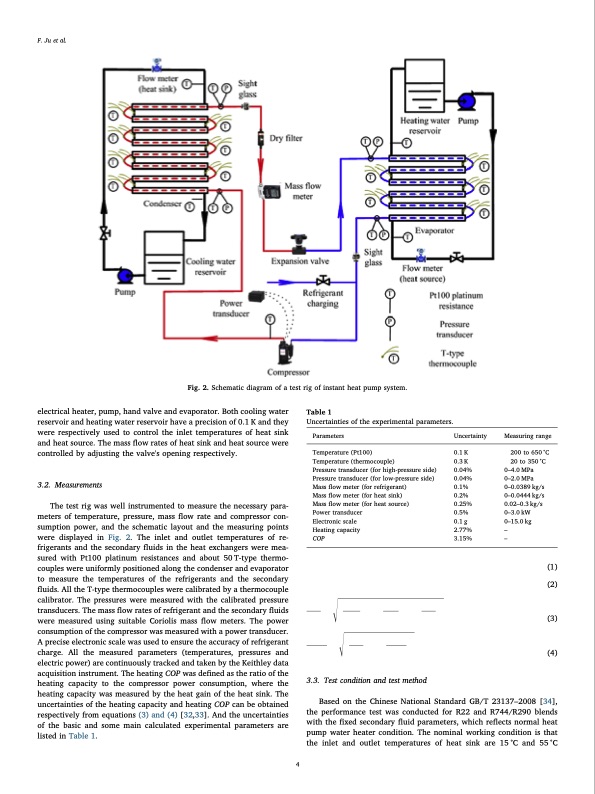
F. Ju et al. �,�Q�W�H�U�Q�D�W�L�R�Q�D�O���-�R�X�U�Q�D�O���R�I���7�K�H�U�P�D�O���6 electrical heater, pump, hand valve and evaporator. Both cooling water reservoir and heating water reservoir have a precision of 0.1 K and they were respectively used to control the inlet temperatures of heat sink and heat source. The mass flow rates of heat sink and heat source were controlled by adjusting the valve's opening respectively. 3.2. Measurements The test rig was well instrumented to measure the necessary para- meters of temperature, pressure, mass flow rate and compressor con- sumption power, and the schematic layout and the measuring points were displayed in Fig. 2. The inlet and outlet temperatures of re- frigerants and the secondary fluids in the heat exchangers were mea- sured with Pt100 platinum resistances and about 50T-type thermo- couples were uniformly positioned along the condenser and evaporator to measure the temperatures of the refrigerants and the secondary fluids. All the T-type thermocouples were calibrated by a thermocouple calibrator. The pressures were measured with the calibrated pressure transducers. The mass flow rates of refrigerant and the secondary fluids were measured using suitable Coriolis mass flow meters. The power consumption of the compressor was measured with a power transducer. A precise electronic scale was used to ensure the accuracy of refrigerant charge. All the measured parameters (temperatures, pressures and electric power) are continuously tracked and taken by the Keithley data acquisition instrument. The heating COP was defined as the ratio of the heating capacity to the compressor power consumption, where the heating capacity was measured by the heat gain of the heat sink. The uncertainties of the heating capacity and heating COP can be obtained respectively from equations (3) and (4) [32,33]. And the uncertainties of the basic and some main calculated experimental parameters are listed in Table 1. Table 1 Uncertainties of the experimental parameters. Parameters Temperature (Pt100) Temperature (thermocouple) Pressure transducer (for high-pressure side) Pressure transducer (for low-pressure side) Mass flow meter (for refrigerant) Mass flow meter (for heat sink) Mass flow meter (for heat source) Power transducer Electronic scale Heating capacity COP Qh=cpm�sk(tsko� tski) COP= Q/ w h com Uncertainty 0.1 K 0.3 K 0.04% 0.04% 0.1% 0.2% 0.25% 0.5% 0.1 g 2.77% 3.15% Measuring range � 200 to 650 °C Fig. 2. Schematic diagram of a test rig of instant heat pump system. � 20to350°C 0–4.0 MPa 0–2.0 MPa 0–0.0389 kg/s 0–0.0444 kg/s 0.02–0.3 kg/s 0–3.0 kW 0–15.0 kg – – �Qh Qh �COP COP � �tsko�2 � m�sk � � tsko � � �Qh�2 � �wcom�2 =��+�� � Qh � � wcom � � �tski�2 � tski � � �m�sk�2 = � � +� � +� � (1) (2) (3) (4) 4 3.3. Test condition and test method Based on the Chinese National Standard GB/T 23137–2008 [34], the performance test was conducted for R22 and R744/R290 blends with the fixed secondary fluid parameters, which reflects normal heat pump water heater condition. The nominal working condition is that the inlet and outlet temperatures of heat sink are 15°C and 55°C �PDF Image | heat pump water heater using R744
PDF Search Title:
heat pump water heater using R744Original File Name Searched:
ZD5177492.pdfDIY PDF Search: Google It | Yahoo | Bing
CO2 Organic Rankine Cycle Experimenter Platform The supercritical CO2 phase change system is both a heat pump and organic rankine cycle which can be used for those purposes and as a supercritical extractor for advanced subcritical and supercritical extraction technology. Uses include producing nanoparticles, precious metal CO2 extraction, lithium battery recycling, and other applications... More Info
Heat Pumps CO2 ORC Heat Pump System Platform More Info
| CONTACT TEL: 608-238-6001 Email: greg@infinityturbine.com | RSS | AMP |