PDF Publication Title:
Text from PDF Page: 011
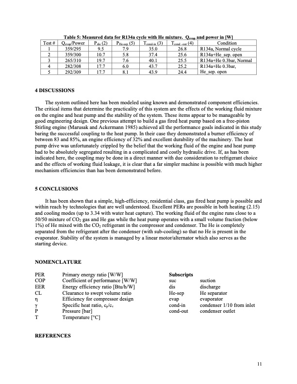
Table 5: Measured data for R134a cycle with He mixture. Qevap and power in [W] Test# Qevap/Power Pdis(2) PHe-sep(5) Tcond-in(3) Tcond–out(4) Condition R134a, Normal cycle R134a+He_sep. open R134a+He 0.3bar, Normal R134a+He 0.3bar, He_sep. open 1 359/295 9.5 7.9 35.0 2 359/300 10.7 5.8 37.4 3 265/310 19.7 7.6 40.1 4 282/308 17.7 6.0 43.7 5 292/309 17.7 8.1 43.9 4 DISCUSSIONS 26.8 25.6 25.5 25.2 24.4 The system outlined here has been modeled using known and demonstrated component efficiencies. The critical items that determine the practicality of this system are the effects of the working fluid mixture on the engine and heat pump and the stability of the system. These items appear to be manageable by good engineering design. One previous attempt to build a gas fired heat pump based on a free-piston Stirling engine (Marusak and Ackermann 1985) achieved all the performance goals indicated in this study baring the successful coupling to the heat pump. In their case they demonstrated a burner efficiency of between 83 and 85%, an engine efficiency of 32% and excellent durability of the machinery. The heat pump drive was unfortunately crippled by the belief that the working fluid of the engine and heat pump had to be absolutely segregated resulting in a complicated and costly hydraulic drive. If, as has been indicated here, the coupling may be done in a direct manner with due consideration to refrigerant choice and the effects of working fluid leakage, it is clear that a far simpler machine is possible with much higher mechanism efficiencies than has been demonstrated before. 5 CONCLUSIONS It has been shown that a simple, high-efficiency, residential class, gas fired heat pump is possible and within reach by technologies that are well understood. Excellent PERs are possible in both heating (2.15) and cooling modes (up to 3.34 with water heat capture). The working fluid of the engine runs close to a 50/50 mixture of CO2 gas and He gas while the heat pump operates with a small volume fraction (below 1%) of He mixed with the CO2 refrigerant in the compressor and condenser. The He is completely separated from the refrigerant after the condenser (with sub-cooling) so that no He is present in the evaporator. Stability of the system is managed by a linear motor/alternator which also serves as the starting device. NOMENCLATURE PER Primary energy ratio [W/W] COP Coefficient of performance [W/W] EER Energy efficiency ratio [Btu/h/W] CL Clearance to swept volume ratio η Efficiency for compressor design γ Specific heat ratio, cp/cv P Pressure [bar] T Temperature [°C] REFERENCES Subscripts suc suction dis discharge He-sep He separator evap evaporator cond-in condenser 1/10 from inlet cond-out condenser outlet 11PDF Image | HERMETIC GAS FIRED RESIDENTIAL HEAT PUMP
PDF Search Title:
HERMETIC GAS FIRED RESIDENTIAL HEAT PUMPOriginal File Name Searched:
Gas_Fired_Heat_Pump.pdfDIY PDF Search: Google It | Yahoo | Bing
CO2 Organic Rankine Cycle Experimenter Platform The supercritical CO2 phase change system is both a heat pump and organic rankine cycle which can be used for those purposes and as a supercritical extractor for advanced subcritical and supercritical extraction technology. Uses include producing nanoparticles, precious metal CO2 extraction, lithium battery recycling, and other applications... More Info
Heat Pumps CO2 ORC Heat Pump System Platform More Info
| CONTACT TEL: 608-238-6001 Email: greg@infinityturbine.com | RSS | AMP |