PDF Publication Title:
Text from PDF Page: 007
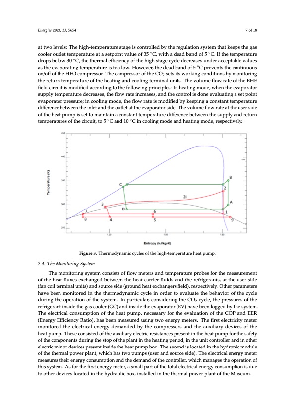
fluids and its critical temperature is around 31 °C. This last characteristic leads to the impossibility of discharging heat to the external air through condensation in a subcritical cycle, when the air temperature, or in general, the heat carrier fluid, is above the critical temperature. The main consequence is that CO2 can be used efficiently for cooling applications when heat is discharged below the critical temperature, while at higher temperatures, when the cycle works at supercritical Energies 2020, 13, 5654 7 of 18 pressures, only gas cooling is possible. Therefore, in cooling applications, the use of the ground as the heat sink is a possible and efficient solution. On the other hand, when the heat pump operates in heating mode, the HVAC (Heating Ventilation Air Conditioning) applications could result more at two levels: The high-temperature stage is controlled by the regulation system that keeps the gas complex because, generally, the supply temperature for the terminal units is above 30 °C, except for cooler outlet temperature at a setpoint value of 35 ◦C, with a dead band of 5 ◦C. If the temperature radiant systems. However, CO2 is a natural fluid, its ODP (ozone depletion potential) is null, it is not drops below 30 ◦C, the thermal efficiency of the high stage cycle decreases under acceptable values flammable and not toxic (A1), and its GWP is equal to 1. For this reason, CO2 was also used in the as the evaporating temperature is too low. However, the dead band of 5 ◦C prevents the continuous past when environmental advantages and safety restrictions reasons overcame the energy on/off of the HFO compressor. The compressor of the CO2 sets its working conditions by monitoring drawbacks. The R1234ze refrigerant is an alternative fluid to the R134a and its environmental impact the return temperature of the heating and cooling terminal units. The volume flow rate of the BHE is lower if compared to the latter. The main properties of the two refrigerants are summarized in field circuit is modified according to the following principles: In heating mode, when the evaporator Table 1. supply temperature decreases, the flow rate increases, and the control is done evaluating a set point The thermodynamic cycles of the heat pump are represented in Figure 3 in a temperature– evaporator pressure; in cooling mode, the flow rate is modified by keeping a constant temperature entropy chart. The diagram shows, from a qualitative point of view, the operating points of the difference between the inlet and the outlet at the evaporator side. The volume flow rate at the user side thermodynamic cycles during the heat pump operations. The letters and the numbers in the chart of the heat pump is set to maintain a constant temperature difference between the supply and return refer to the points reported in Figure 2, which shows the scheme of the heat pump’s high and low- temperatures of the circuit, to 5 ◦C and 10 ◦C in cooling mode and heating mode, respectively. temperature cycles. Figure 3. Thermodynamic cycles of the high-temperature heat pump. Figure 3. Thermodynamic cycles of the high-temperature heat pump. 2.4. The Monitoring System The monitoring system consists of flow meters and temperature probes for the measurement of the heat fluxes exchanged between the heat carrier fluids and the refrigerants, at the user side (fan coil terminal units) and source side (ground heat exchangers field), respectively. Other parameters have been monitored in the thermodynamic cycle in order to evaluate the behavior of the cycle during the operation of the system. In particular, considering the CO2 cycle, the pressures of the refrigerant inside the gas cooler (GC) and inside the evaporator (EV) have been logged by the system. The electrical consumption of the heat pump, necessary for the evaluation of the COP and EER (Energy Efficiency Ratio), has been measured using two energy meters. The first electricity meter monitored the electrical energy demanded by the compressors and the auxiliary devices of the heat pump. These consisted of the auxiliary electric resistances present in the heat pump for the safety of the components during the stop of the plant in the heating period, in the unit controller and in other electric minor devices present inside the heat pump box. The second is located in the hydronic module of the thermal power plant, which has two pumps (user and source side). The electrical energy meter measures their energy consumption and the demand of the controller, which manages the operation of this system. As for the first energy meter, a small part of the total electrical energy consumption is due to other devices located in the hydraulic box, installed in the thermal power plant of the Museum.PDF Image | Novel Ground-Source Heat Pump with R744
PDF Search Title:
Novel Ground-Source Heat Pump with R744Original File Name Searched:
energies-13-05654.pdfDIY PDF Search: Google It | Yahoo | Bing
CO2 Organic Rankine Cycle Experimenter Platform The supercritical CO2 phase change system is both a heat pump and organic rankine cycle which can be used for those purposes and as a supercritical extractor for advanced subcritical and supercritical extraction technology. Uses include producing nanoparticles, precious metal CO2 extraction, lithium battery recycling, and other applications... More Info
Heat Pumps CO2 ORC Heat Pump System Platform More Info
| CONTACT TEL: 608-238-6001 Email: greg@infinityturbine.com | RSS | AMP |