PDF Publication Title:
Text from PDF Page: 017
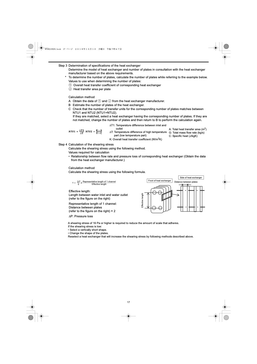
Step 3 Determination of specifications of the heat exchanger Determine the model of heat exchanger and number of plates in consultation with the heat exchanger manufacturer based on the above requirements. * To determine the number of plates, calculate the number of plates while referring to the example below. Values to use when determining the number of plates: 1 Overall heat transfer coefficient of corresponding heat exchanger 2 Heat transfer area per plate Calculation method A Obtain the data of 1 and 2 from the heat exchanger manufacturer. B Estimate the number of plates of the heat exchanger. C Check that the number of transfer units for the corresponding number of plates matches between NTU1 and NTU2 (NTU1=NTU2). If they are matched, select a heat exchanger having the corresponding number of plates. If they are not matched, change the number of plates and then return to B to perform the calculation again. T1 KA NTU1 = ----- NTU2 = --- T VC ∆T1: Temperature difference between inlet and outlet ∆T: Temperature difference of high temperature part (low temperature part) K: Overall heat transfer coefficient (W/m2K) A: Total heat transfer area (m2) G: Total mass flow rate (kg/s) C: Specific heat (J/kgK) Step 4 Calculation of the shearing stress Calculate the shearing stress using the following method. Values required for calculation • Relationship between flow rate and pressure loss of corresponding heat exchanger (Obtain the data from the heat exchanger manufacturer.) Calculation method Calculate the shearing stress using the following formula. Effective length: Length between water inlet and water outlet (refer to the figure on the right) Representative length of 1 channel: Distance between plates (refer to the figure on the right) × 2 ∆P: Pressure loss Side of heat exchanger Representative length of 1 channel Effective length A shearing stress of 16 Pa or higher is required to reduce the amount of scale that adheres. If the shearing stress is low: • Select a vertically short shape. • Change the shape of the plates. Reselect a heat exchanger that will increase the shearing stress by following methods described above. 17 Front of heat exchanger Distance between plates Effective lengthPDF Image | QAHV-N560YA-HPB
PDF Search Title:
QAHV-N560YA-HPBOriginal File Name Searched:
IBIM_WT08219X05_QAHV_N560YA_HPB_ML.pdfDIY PDF Search: Google It | Yahoo | Bing
CO2 Organic Rankine Cycle Experimenter Platform The supercritical CO2 phase change system is both a heat pump and organic rankine cycle which can be used for those purposes and as a supercritical extractor for advanced subcritical and supercritical extraction technology. Uses include producing nanoparticles, precious metal CO2 extraction, lithium battery recycling, and other applications... More Info
Heat Pumps CO2 ORC Heat Pump System Platform More Info
| CONTACT TEL: 608-238-6001 Email: greg@infinityturbine.com | RSS | AMP |