PDF Publication Title:
Text from PDF Page: 016
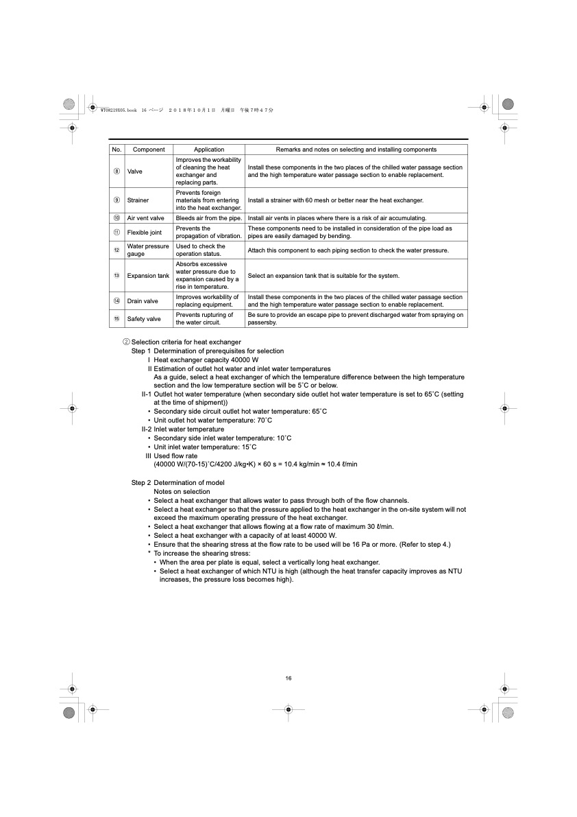
No. Component Application Remarks and notes on selecting and installing components 8 Valve Improves the workability of cleaning the heat exchanger and replacing parts. Install these components in the two places of the chilled water passage section and the high temperature water passage section to enable replacement. 9 Strainer Prevents foreign materials from entering into the heat exchanger. Install a strainer with 60 mesh or better near the heat exchanger. 0 Air vent valve Bleeds air from the pipe. Install air vents in places where there is a risk of air accumulating. a Flexible joint Prevents the propagation of vibration. These components need to be installed in consideration of the pipe load as pipes are easily damaged by bending. b Water pressure gauge Used to check the operation status. Attach this component to each piping section to check the water pressure. c Expansion tank Absorbs excessive water pressure due to expansion caused by a rise in temperature. Select an expansion tank that is suitable for the system. d Drain valve Improves workability of replacing equipment. Install these components in the two places of the chilled water passage section and the high temperature water passage section to enable replacement. e Safety valve Prevents rupturing of the water circuit. Be sure to provide an escape pipe to prevent discharged water from spraying on passersby. 2 Selection criteria for heat exchanger Step 1 I II II-1 • • II-2 • • III Step 2 • • • • • * Determination of prerequisites for selection Heat exchanger capacity 40000 W Estimation of outlet hot water and inlet water temperatures As a guide, select a heat exchanger of which the temperature difference between the high temperature section and the low temperature section will be 5 ̊C or below. Outlet hot water temperature (when secondary side outlet hot water temperature is set to 65 ̊C (setting at the time of shipment)) Secondary side circuit outlet hot water temperature: 65 ̊C Unit outlet hot water temperature: 70 ̊C Inlet water temperature Secondary side inlet water temperature: 10 ̊C Unit inlet water temperature: 15 ̊C Used flow rate (40000 W/(70-15) ̊C/4200 J/kg•K) × 60 s = 10.4 kg/min ≈ 10.4 l/min Determination of model Notes on selection Select a heat exchanger that allows water to pass through both of the flow channels. Select a heat exchanger so that the pressure applied to the heat exchanger in the on-site system will not exceed the maximum operating pressure of the heat exchanger. Select a heat exchanger that allows flowing at a flow rate of maximum 30 l/min. Select a heat exchanger with a capacity of at least 40000 W. Ensure that the shearing stress at the flow rate to be used will be 16 Pa or more. (Refer to step 4.) To increase the shearing stress: • When the area per plate is equal, select a vertically long heat exchanger. • Select a heat exchanger of which NTU is high (although the heat transfer capacity improves as NTU increases, the pressure loss becomes high). 16PDF Image | QAHV-N560YA-HPB
PDF Search Title:
QAHV-N560YA-HPBOriginal File Name Searched:
IBIM_WT08219X05_QAHV_N560YA_HPB_ML.pdfDIY PDF Search: Google It | Yahoo | Bing
CO2 Organic Rankine Cycle Experimenter Platform The supercritical CO2 phase change system is both a heat pump and organic rankine cycle which can be used for those purposes and as a supercritical extractor for advanced subcritical and supercritical extraction technology. Uses include producing nanoparticles, precious metal CO2 extraction, lithium battery recycling, and other applications... More Info
Heat Pumps CO2 ORC Heat Pump System Platform More Info
| CONTACT TEL: 608-238-6001 Email: greg@infinityturbine.com | RSS | AMP |