PDF Publication Title:
Text from PDF Page: 215
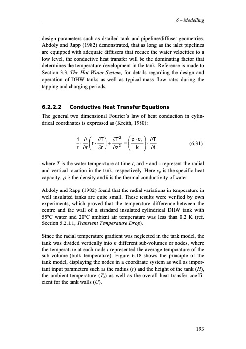
design parameters such as detailed tank and pipeline/diffuser geometries. Abdoly and Rapp (1982) demonstrated, that as long as the inlet pipelines are equipped with adequate diffusers that reduce the water velocities to a low level, the conductive heat transfer will be the dominating factor that determines the temperature development in the tank. Reference is made to Section 3.3, The Hot Water System, for details regarding the design and operation of DHW tanks as well as typical mass flow rates during the tapping and charging periods. 6.2.2.2 Conductive Heat Transfer Equations The general two dimensional Fourier’s law of heat conduction in cylin- drical coordinates is expressed as (Kreith, 1980): 1∂⎛ ∂T⎞ ∂T2 ⎛ρ⋅cp⎞∂T r⋅∂r⎜⎝r⋅∂r⎟⎠+∂z2 =⎜ k ⎟⋅∂t (6.31) ⎝⎠ where T is the water temperature at time t, and r and z represent the radial and vertical location in the tank, respectively. Here cp is the specific heat capacity, ρ is the density and k is the thermal conductivity of water. Abdoly and Rapp (1982) found that the radial variations in temperature in well insulated tanks are quite small. These results were verified by own experiments, which proved that the temperature difference between the centre and the wall of a standard insulated cylindrical DHW tank with 55oC water and 20oC ambient air temperature was less than 0.2 K (ref. Section 5.2.1.1, Transient Temperature Drop). Since the radial temperature gradient was neglected in the tank model, the tank was divided vertically into n different sub-volumes or nodes, where the temperature at each node i represented the average temperature of the sub-volume (bulk temperature). Figure 6.18 shows the principle of the tank model, displaying the nodes in a coordinate system as well as impor- tant input parameters such as the radius (r) and the height of the tank (H), the ambient temperature (TA) as well as the overall heat transfer coeffi- cient for the tank walls (U). 6 – Modelling 193PDF Image | Residential CO2 Heat Pump System for Combined

PDF Search Title:
Residential CO2 Heat Pump System for CombinedOriginal File Name Searched:
20559406.pdfDIY PDF Search: Google It | Yahoo | Bing
CO2 Organic Rankine Cycle Experimenter Platform The supercritical CO2 phase change system is both a heat pump and organic rankine cycle which can be used for those purposes and as a supercritical extractor for advanced subcritical and supercritical extraction technology. Uses include producing nanoparticles, precious metal CO2 extraction, lithium battery recycling, and other applications... More Info
Heat Pumps CO2 ORC Heat Pump System Platform More Info
| CONTACT TEL: 608-238-6001 Email: greg@infinityturbine.com | RSS | AMP |