PDF Publication Title:
Text from PDF Page: 216
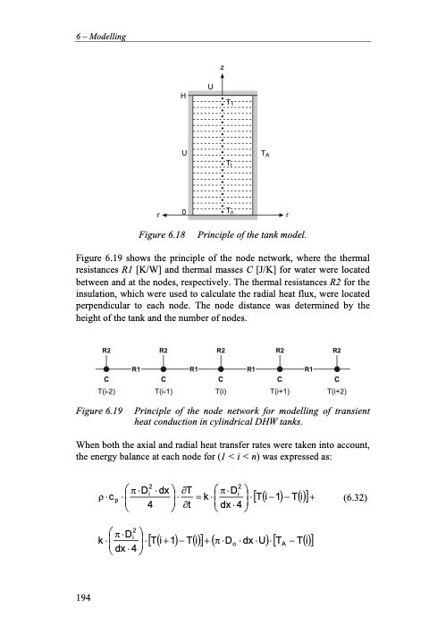
6 – Modelling z U H U TA r0r Figure 6.18 Principle of the tank model. Figure 6.19 shows the principle of the node network, where the thermal resistances R1 [K/W] and thermal masses C [J/K] for water were located between and at the nodes, respectively. The thermal resistances R2 for the insulation, which were used to calculate the radial heat flux, were located perpendicular to each node. The node distance was determined by the height of the tank and the number of nodes. R2 R2 R2 R2 R2 R1 R1 R1 R1 CCCCC T(i-2) T(i-1) T(i) T(i+1) T(i+2) Figure 6.19 Principle of the node network for modelling of transient heat conduction in cylindrical DHW tanks. When both the axial and radial heat transfer rates were taken into account, the energy balance at each node for (1 < i < n) was expressed as: (6.32) T1 Ti Tn p⎜i ⎟ ⎜i⎟ ρ⋅c ⋅⎛π⋅D2 ⋅dx⎞⋅∂T =k⋅⎛π⋅D2 ⎞⋅[T(i−1)−T(i)]+ ⎝ 4 ⎠∂t ⎝dx⋅4⎠ k⋅⎛π⋅D2 ⎞⋅[T(i+1)−T(i)]+(π⋅D ⋅dx⋅U)⋅[T −T(i)] ⎜i⎟ o A ⎝ dx ⋅ 4 ⎠ 194PDF Image | Residential CO2 Heat Pump System for Combined
PDF Search Title:
Residential CO2 Heat Pump System for CombinedOriginal File Name Searched:
20559406.pdfDIY PDF Search: Google It | Yahoo | Bing
CO2 Organic Rankine Cycle Experimenter Platform The supercritical CO2 phase change system is both a heat pump and organic rankine cycle which can be used for those purposes and as a supercritical extractor for advanced subcritical and supercritical extraction technology. Uses include producing nanoparticles, precious metal CO2 extraction, lithium battery recycling, and other applications... More Info
Heat Pumps CO2 ORC Heat Pump System Platform More Info
| CONTACT TEL: 608-238-6001 Email: greg@infinityturbine.com | RSS | AMP |