PDF Publication Title:
Text from PDF Page: 026
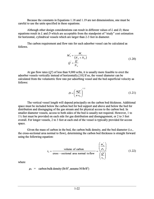
Because the constants in Equations 1.18 and 1.19 are not dimensionless, one must be careful to use the units specified in these equations. Although other design considerations can result in different values of L and D, these equations result in L and D which are acceptable from the standpoint of “study” cost estimation for horizontal, cylindrical vessels which are larger than 2-3 feet in diameter. The carbon requirement and flow rate for each adsorber vessel can be calculated as follows. where ρb = carbon bulk density (lb/ft3, assume 30 lb/ft3) tb volume of carbon cross sectional area normal toflow b Q' (1.22) M'Mc c NA ND Q ' NQ A (1.20) At gas flow rates (Q') of less than 9,000 scfm, it is usually more feasible to erect the adsorber vessels vertically instead of horizontally.[10] If so, the vessel diameter can be calculated from the volumetric flow rate per adsorbing vessel and the bed superficial velocity as follows: (1.21) The vertical vessel length will depend principally on the carbon bed thickness. Additional space must be included below the carbon bed for bed support and above and below the bed for distribution and disengaging of the gas stream and for physical access to the carbon bed. In smaller diameter vessels, access to both sides of the bed is usually not required. However, 1 to 11⁄2 feet must be provided on each side for gas distribution and disengagement, or 2 to 3 feet overall. For longer vessels, 2 to 3 feet at each end of the vessel is typically provided for access space. Given the mass of carbon in the bed, the carbon bulk density, and the bed diameter (i.e., the cross-sectional area normal to flow), determining the carbon bed thickness is straight forward using the following equation: 1/2 4Q' Dv b M' c v b 1-22PDF Image | Carbon Adsorbers

PDF Search Title:
Carbon AdsorbersOriginal File Name Searched:
final_carbonadsorberschapter_7thedition.pdfDIY PDF Search: Google It | Yahoo | Bing
CO2 Organic Rankine Cycle Experimenter Platform The supercritical CO2 phase change system is both a heat pump and organic rankine cycle which can be used for those purposes and as a supercritical extractor for advanced subcritical and supercritical extraction technology. Uses include producing nanoparticles, precious metal CO2 extraction, lithium battery recycling, and other applications... More Info
Heat Pumps CO2 ORC Heat Pump System Platform More Info
| CONTACT TEL: 608-238-6001 Email: greg@infinityturbine.com | RSS | AMP |