PDF Publication Title:
Text from PDF Page: 025
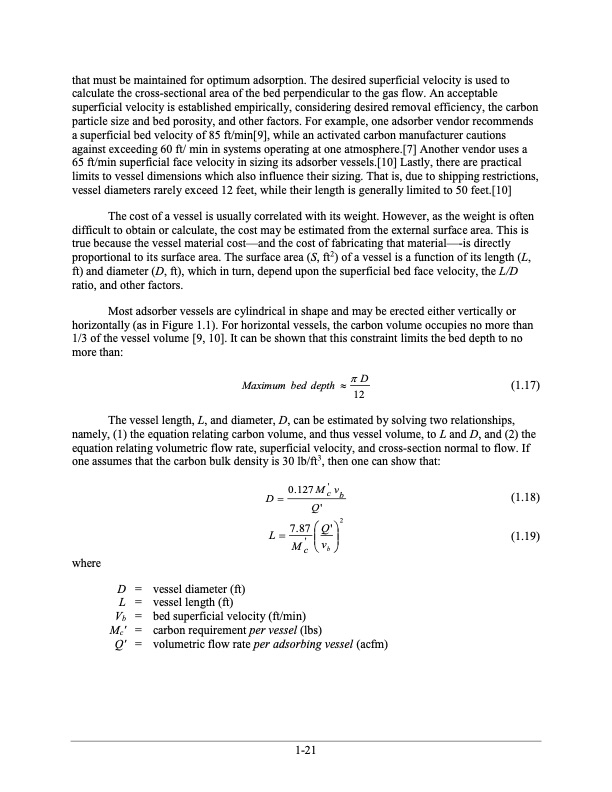
that must be maintained for optimum adsorption. The desired superficial velocity is used to calculate the cross-sectional area of the bed perpendicular to the gas flow. An acceptable superficial velocity is established empirically, considering desired removal efficiency, the carbon particle size and bed porosity, and other factors. For example, one adsorber vendor recommends a superficial bed velocity of 85 ft/min[9], while an activated carbon manufacturer cautions against exceeding 60 ft/ min in systems operating at one atmosphere.[7] Another vendor uses a 65 ft/min superficial face velocity in sizing its adsorber vessels.[10] Lastly, there are practical limits to vessel dimensions which also influence their sizing. That is, due to shipping restrictions, vessel diameters rarely exceed 12 feet, while their length is generally limited to 50 feet.[10] The cost of a vessel is usually correlated with its weight. However, as the weight is often difficult to obtain or calculate, the cost may be estimated from the external surface area. This is true because the vessel material cost—and the cost of fabricating that material—-is directly proportional to its surface area. The surface area (S, ft2) of a vessel is a function of its length (L, ft) and diameter (D, ft), which in turn, depend upon the superficial bed face velocity, the L/D ratio, and other factors. Most adsorber vessels are cylindrical in shape and may be erected either vertically or horizontally (as in Figure 1.1). For horizontal vessels, the carbon volume occupies no more than 1/3 of the vessel volume [9, 10]. It can be shown that this constraint limits the bed depth to no more than: Maximum bed depth D (1.17) 12 The vessel length, L, and diameter, D, can be estimated by solving two relationships, namely, (1) the equation relating carbon volume, and thus vessel volume, to L and D, and (2) the equation relating volumetric flow rate, superficial velocity, and cross-section normal to flow. If one assumes that the carbon bulk density is 30 lb/ft3, then one can show that: where D = L = Vb = Mc' = Q' = vessel diameter (ft) vessel length (ft) bed superficial velocity (ft/min) carbon requirement per vessel (lbs) volumetric flow rate per adsorbing vessel (acfm) 0.127M' v D cb (1.18) (1.19) Q' 7.87 Q'2 L M' v cb 1-21PDF Image | Carbon Adsorbers

PDF Search Title:
Carbon AdsorbersOriginal File Name Searched:
final_carbonadsorberschapter_7thedition.pdfDIY PDF Search: Google It | Yahoo | Bing
CO2 Organic Rankine Cycle Experimenter Platform The supercritical CO2 phase change system is both a heat pump and organic rankine cycle which can be used for those purposes and as a supercritical extractor for advanced subcritical and supercritical extraction technology. Uses include producing nanoparticles, precious metal CO2 extraction, lithium battery recycling, and other applications... More Info
Heat Pumps CO2 ORC Heat Pump System Platform More Info
| CONTACT TEL: 608-238-6001 Email: greg@infinityturbine.com | RSS | AMP |