PDF Publication Title:
Text from PDF Page: 013
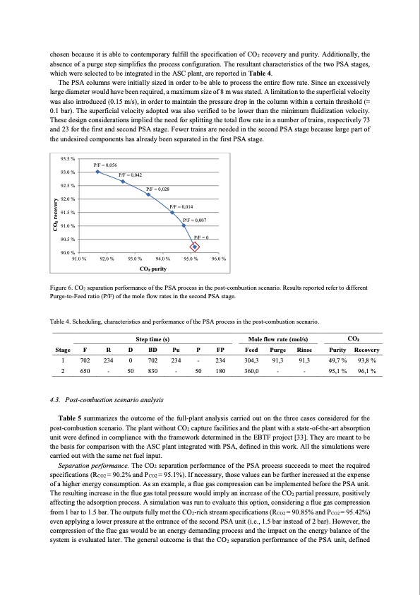
chosen because it is able to contemporary fulfill the specification of CO2 recovery and purity. Additionally, the absence of a purge step simplifies the process configuration. The resultant characteristics of the two PSA stages, which were selected to be integrated in the ASC plant, are reported in Table 4. The PSA columns were initially sized in order to be able to process the entire flow rate. Since an excessively large diameter would have been required, a maximum size of 8 m was stated. A limitation to the superficial velocity was also introduced (0.15 m/s), in order to maintain the pressure drop in the column within a certain threshold (≈ 0.1 bar). The superficial velocity adopted was also verified to be lower than the minimum fluidization velocity. These design considerations implied the need for splitting the total flow rate in a number of trains, respectively 73 and 23 for the first and second PSA stage. Fewer trains are needed in the second PSA stage because large part of the undesired components has already been separated in the first PSA stage. 93.5 % 93.0 % 92.5 % 92.0 % 91.5 % 91.0 % 90.5 % 90.0 % 91.0 % P/F = 0,056 P/F = 0,042 92.0 % P/F = 0,028 P/F = 0,014 P/F = 0,007 93.0 % 94.0 % P/F = 0 95.0 % 96.0 % CO2 purity Figure 6. CO2 separation performance of the PSA process in the post-combustion scenario. Results reported refer to different Purge-to-Feed ratio (P/F) of the mole flow rates in the second PSA stage. Table 4. Scheduling, characteristics and performance of the PSA process in the post-combustion scenario. Step time (s) Mole flow rate (mol/s) CO2 Stage F R D BD Pu P FP Feed Purge Rinse Purity Recovery 1 702 234 0 702 234 - 234 304,3 91,3 91,3 49,7 % 93,8 % 2 650 - 50 830 - 50 180 360,0 - - 95,1% 96,1% 4.3. Post-combustion scenario analysis Table 5 summarizes the outcome of the full-plant analysis carried out on the three cases considered for the post-combustion scenario. The plant without CO2 capture facilities and the plant with a state-of-the-art absorption unit were defined in compliance with the framework determined in the EBTF project [33]. They are meant to be the basis for comparison with the ASC plant integrated with PSA, defined in this work. All the simulations were carried out with the same net fuel input. Separation performance. The CO2 separation performance of the PSA process succeeds to meet the required specifications (RCO2 = 90.2% and PCO2 = 95.1%). If necessary, those values can be further increased at the expense of a higher energy consumption. As an example, a flue gas compression can be implemented before the PSA unit. The resulting increase in the flue gas total pressure would imply an increase of the CO2 partial pressure, positively affecting the adsorption process. A simulation was run to evaluate this option, considering a flue gas compression from 1 bar to 1.5 bar. The outputs fully met the CO2-rich stream specifications (RCO2 = 90.85% and PCO2 = 95.42%) even applying a lower pressure at the entrance of the second PSA unit (i.e., 1.5 bar instead of 2 bar). However, the compression of the flue gas would be an energy demanding process and the impact on the energy balance of the system is evaluated later. The general outcome is that the CO2 separation performance of the PSA unit, defined CO2 recoveryPDF Image | Evaluating Pressure Swing Adsorption as a CO2 separation technique in coal-fired
PDF Search Title:
Evaluating Pressure Swing Adsorption as a CO2 separation technique in coal-firedOriginal File Name Searched:
PSA-coal-fired-plants.pdfDIY PDF Search: Google It | Yahoo | Bing
CO2 Organic Rankine Cycle Experimenter Platform The supercritical CO2 phase change system is both a heat pump and organic rankine cycle which can be used for those purposes and as a supercritical extractor for advanced subcritical and supercritical extraction technology. Uses include producing nanoparticles, precious metal CO2 extraction, lithium battery recycling, and other applications... More Info
Heat Pumps CO2 ORC Heat Pump System Platform More Info
| CONTACT TEL: 608-238-6001 Email: greg@infinityturbine.com | RSS | AMP |