PDF Publication Title:
Text from PDF Page: 099
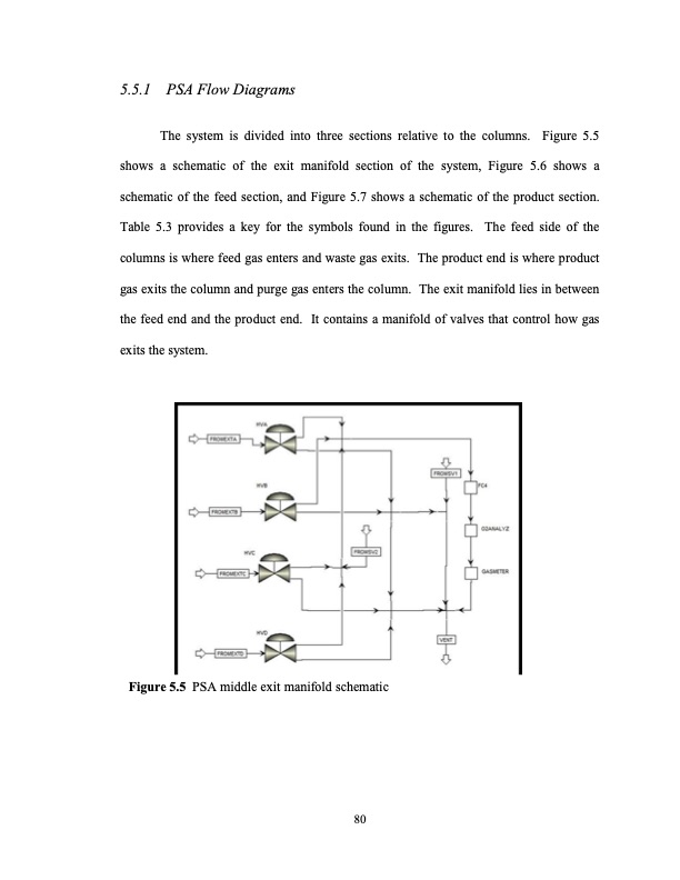
5.5.1 PSA Flow Diagrams The system is divided into three sections relative to the columns. Figure 5.5 shows a schematic of the exit manifold section of the system, Figure 5.6 shows a schematic of the feed section, and Figure 5.7 shows a schematic of the product section. Table 5.3 provides a key for the symbols found in the figures. The feed side of the columns is where feed gas enters and waste gas exits. The product end is where product gas exits the column and purge gas enters the column. The exit manifold lies in between the feed end and the product end. It contains a manifold of valves that control how gas exits the system. Figure 5.5 PSA middle exit manifold schematic 80PDF Image | LIMITS OF SMALL SCALE PRESSURE SWING ADSORPTION
PDF Search Title:
LIMITS OF SMALL SCALE PRESSURE SWING ADSORPTIONOriginal File Name Searched:
Limits of Small Scale PSA_Aaron Moran.pdfDIY PDF Search: Google It | Yahoo | Bing
CO2 Organic Rankine Cycle Experimenter Platform The supercritical CO2 phase change system is both a heat pump and organic rankine cycle which can be used for those purposes and as a supercritical extractor for advanced subcritical and supercritical extraction technology. Uses include producing nanoparticles, precious metal CO2 extraction, lithium battery recycling, and other applications... More Info
Heat Pumps CO2 ORC Heat Pump System Platform More Info
| CONTACT TEL: 608-238-6001 Email: greg@infinityturbine.com | RSS | AMP |