PDF Publication Title:
Text from PDF Page: 015
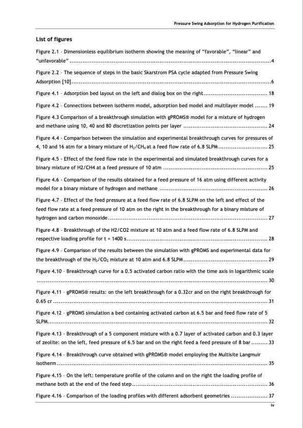
List of figures Figure 2.1 – Dimensionless equilibrium isotherm showing the meaning of “favorable”, “linear” and “unfavorable” ..............................................................................................................4 Figure 2.2 – The sequence of steps in the basic Skarstrom PSA cycle adapted from Pressure Swing Adsorption [10].............................................................................................................6 Figure 4.1 – Adsorption bed layout on the left and dialog box on the right................................... 18 Figure 4.2 – Connections between isotherm model, adsorption bed model and multilayer model ....... 19 Figure 4.3 Comparison of a breakthrough simulation with gPROMS® model for a mixture of hydrogen and methane using 10, 40 and 80 discretization points per layer .............................................. 24 Figure 4.4 - Comparison between the simulation and experimental breakthrough curves for pressures of 4, 10 and 16 atm for a binary mixture of H2/CH4 at a feed flow rate of 6.8 SLPM ........................... 25 Figure 4.5 - Effect of the feed flow rate in the experimental and simulated breakthrough curves for a binary mixture of H2/CH4 at a feed pressure of 10 atm ......................................................... 25 Figure 4.6 - Comparison of the results obtained for a feed pressure of 16 atm using different activity model for a binary mixture of hydrogen and methane ........................................................... 26 Figure 4.7 – Effect of the feed pressure at a feed flow rate of 6.8 SLPM on the left and effect of the feed flow rate at a feed pressure of 10 atm on the right in the breakthrough for a binary mixture of hydrogen and carbon monoxide ....................................................................................... 27 Figure 4.8 – Breakthrough of the H2/CO2 mixture at 10 atm and a feed flow rate of 6.8 SLPM and respective loading profile for t = 1400 s............................................................................. 28 Figure 4.9 – Comparison of the results between the simulation with gPROMS and experimental data for the breakthrough of the H2/CO2 mixture at 10 atm and 6.8 SLPM .............................................. 29 Figure 4.10 – Breakthrough curve for a 0.5 activated carbon ratio with the time axis in logarithmic scale .............................................................................................................................. 30 Figure 4.11 – gPROMS® results: on the left breakthrough for a 0.32cr and on the right breakthrough for 0.65 cr ..................................................................................................................... 31 Figure 4.12 – gPROMS simulation a bed containing activated carbon at 6.5 bar and feed flow rate of 5 SLPM........................................................................................................................ 32 Figure 4.13 - Breakthrough of a 5 component mixture with a 0.7 layer of activated carbon and 0.3 layer of zeolite: on the left, feed pressure of 6.5 bar and on the right feed a feed pressure of 8 bar ......... 33 Figure 4.14 – Breakthrough curve obtained with gPROMS® model employing the Multisite Langmuir isotherm ................................................................................................................... 35 Figure 4.15 – On the left: temperature profile of the column and on the right the loading profile of methane both at the end of the feed step.......................................................................... 36 Figure 4.16 – Comparison of the loading profiles with different adsorbent geometries .................... 37 Pressure Swing Adsorption for Hydrogen Purification ivPDF Image | PRESSURE SWING ADSORPTION FOR THE PURIFICATION OF HYDROGEN

PDF Search Title:
PRESSURE SWING ADSORPTION FOR THE PURIFICATION OF HYDROGENOriginal File Name Searched:
32541.pdfDIY PDF Search: Google It | Yahoo | Bing
CO2 Organic Rankine Cycle Experimenter Platform The supercritical CO2 phase change system is both a heat pump and organic rankine cycle which can be used for those purposes and as a supercritical extractor for advanced subcritical and supercritical extraction technology. Uses include producing nanoparticles, precious metal CO2 extraction, lithium battery recycling, and other applications... More Info
Heat Pumps CO2 ORC Heat Pump System Platform More Info
| CONTACT TEL: 608-238-6001 Email: greg@infinityturbine.com | RSS | AMP |