PDF Publication Title:
Text from PDF Page: 121
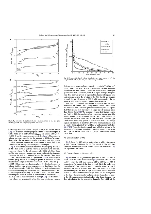
A. Mosca et al. / Microporous and Mesoporous Materials 120 (2009) 195–205 201 Fig. 6. Mesopore (2–50 nm) volume distribution per gram zeolite of MFI film samples C48-6, C48-13, C96-9, G, and reference crystals DC72. Fig. 5. N2 adsorption–desorption isotherm per gram sample (a) and per gram zeolite (b) of MFI film samples prepared in this work. 0.16 cm3/g zeolite for all film samples, as expected for MFI zeolite [23]. The mesopore volume per gram sample of the film samples is 0.005, 0.010, 0.015 and 0.009 cm3/gsample, for sample C48-6, C48- 13, C96-9, and G, respectively, as reported in Table 1. The mesopore volume per gram sample for the support is 0.001 cm3/g, which shows that the mesopores mostly originates from the zeolite film.The mesopore volume per gram sample is about 2–3 times lower than the micropore volume per gram sample. Fig. 6 shows the cumulative mesopore volume per g zeolite of all MFI film samples and the reference powder DC72. The total mesopore volume for the reference powder DC72 is 0.06 cm3/gzeo- lite. The total mesopore volumes per gram zeolite of the film sam- ples are 0.09, 0.10, and 0.11 cm3/gzeolite, for samples C48-6, C48- 13, and C96-9, respectively, as reported in Table 1. The mesopore volume per g zeolite of the samples grown in the clear solution is in the same range as the mesopore volume (0.075–0.16 cm3 g1) in ZSM-5 films grown on alumina spheres [9]. The total mesopore volume for films grown in the clear solution is thus higher than for the reference powder DC72. This difference is assigned to mesop- ores in the form of grain boundaries and cracks in the films formed during template removal by calcination at 550 °C. It is well known that template removal results in contraction of MFI crystals [24] and may lead to crack formation in films [25,26]. The total meso- pore volume per gram zeolite of the film grown in the gel (sample G) is the same as the reference powder crystals DC72 (0.06 cm3/ gzeolite). In concert with the SEM observations, the low mesopore volume of the film sample G indicates that it is free from open grain boundaries and cracks, at least at liquid nitrogen tempera- ture. This film was grown in a gel in the absence of organic tem- plate molecules, and the crystals in the film should not contract as much during calcination at 550 °C, which may explain the ab- sence of additional mesopores compared to sample DC72. The mesopore volume distribution is shifted towards larger mesopores for sample C48-13 compared to sample C48-6, which has a thinner film. This is in agreement with our previous reports that thicker films may have more of larger defects such as cracks than thinner films [8,9]. The mesopore volume distribution of sam- ple C96-9 is shifted towards smaller mesopores, although the film on this sample it is as thick as on sample C48-13. This difference is assigned to that the upper part of this film is of sandwich type rather than epitaxially grown as discussed earlier. The average crystal size in films of sandwich type will be much smaller than in equally thick, epitaxially grown films as we have reported before [22,27,28]. This reduction in crystals size is likely resulting in the formation of small grain boundaries (small mesopores) in-between the crystals rather than cracks (larger mesopores) during calcination. 3.4. Characterization by XRD Fig. 7 shows the XRD pattern for the discrete MFI crystals grown in 72 h (sample DC72) and for the film sample G. The XRD data show that the samples consist of MFI and cordierite crystals [29], see Figure text for details. 3.5. Characterization by NO2 adsorption Fig. 8a shows the NO2 breakthrough curves at 30 °C. The time to reach 5% of the outlet concentration [30] occurred after 62, 232, and 364 s for the MFI film samples C48-6, C48-13, and C96-9, respectively. As expected, the time to reach 5% of the outlet con- centration is linked to the adsorption capacity, which in turn is linked to the zeolite loading, which was 0.06, 0.10 and 0.14 g/g for these samples, and also to Si/Al ratio, which will be discussed below. The shape of the breakthrough fronts for the films grown in the clear solution is similar and characterized by a steep increase in the NO2 concentration, indicating low axial dispersion and even flow distribution in the monolith channels. The width of thePDF Image | Structured Zeolite Adsorbents for PSA Applications
PDF Search Title:
Structured Zeolite Adsorbents for PSA ApplicationsOriginal File Name Searched:
structured-zeolites.pdfDIY PDF Search: Google It | Yahoo | Bing
CO2 Organic Rankine Cycle Experimenter Platform The supercritical CO2 phase change system is both a heat pump and organic rankine cycle which can be used for those purposes and as a supercritical extractor for advanced subcritical and supercritical extraction technology. Uses include producing nanoparticles, precious metal CO2 extraction, lithium battery recycling, and other applications... More Info
Heat Pumps CO2 ORC Heat Pump System Platform More Info
| CONTACT TEL: 608-238-6001 Email: greg@infinityturbine.com | RSS | AMP |