PDF Publication Title:
Text from PDF Page: 014
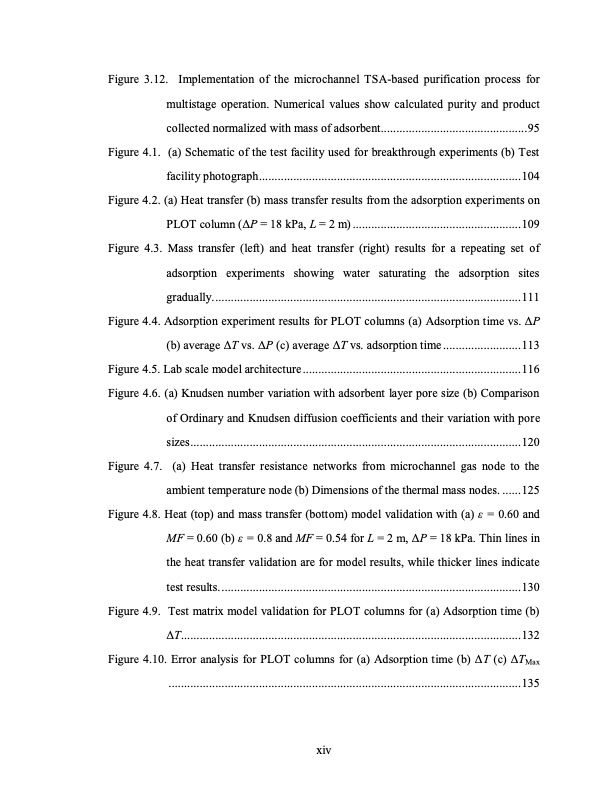
Figure 3.12. Implementation of the microchannel TSA-based purification process for multistage operation. Numerical values show calculated purity and product collected normalized with mass of adsorbent...............................................95 Figure 4.1. (a) Schematic of the test facility used for breakthrough experiments (b) Test facility photograph....................................................................................104 Figure 4.2. (a) Heat transfer (b) mass transfer results from the adsorption experiments on PLOT column (ΔP = 18 kPa, L = 2 m) ......................................................109 Figure 4.3. Mass transfer (left) and heat transfer (right) results for a repeating set of adsorption experiments showing water saturating the adsorption sites gradually...................................................................................................111 Figure 4.4. Adsorption experiment results for PLOT columns (a) Adsorption time vs. ΔP (b) average ΔT vs. ΔP (c) average ΔT vs. adsorption time .........................113 Figure 4.5. Lab scale model architecture......................................................................116 Figure 4.6. (a) Knudsen number variation with adsorbent layer pore size (b) Comparison of Ordinary and Knudsen diffusion coefficients and their variation with pore sizes..........................................................................................................120 Figure 4.7. (a) Heat transfer resistance networks from microchannel gas node to the ambient temperature node (b) Dimensions of the thermal mass nodes. ......125 Figure 4.8. Heat (top) and mass transfer (bottom) model validation with (a) ε = 0.60 and MF = 0.60 (b) ε = 0.8 and MF = 0.54 for L = 2 m, ΔP = 18 kPa. Thin lines in the heat transfer validation are for model results, while thicker lines indicate test results.................................................................................................130 Figure 4.9. Test matrix model validation for PLOT columns for (a) Adsorption time (b) ΔT.............................................................................................................132 Figure 4.10. Error analysis for PLOT columns for (a) Adsorption time (b) ΔT (c) ΔTMax .................................................................................................................135 xivPDF Image | TEMPERATURE SWING ADSORPTION PROCESSES FOR GAS SEPARATION

PDF Search Title:
TEMPERATURE SWING ADSORPTION PROCESSES FOR GAS SEPARATIONOriginal File Name Searched:
PAHINKAR-DISSERTATION-2016.pdfDIY PDF Search: Google It | Yahoo | Bing
CO2 Organic Rankine Cycle Experimenter Platform The supercritical CO2 phase change system is both a heat pump and organic rankine cycle which can be used for those purposes and as a supercritical extractor for advanced subcritical and supercritical extraction technology. Uses include producing nanoparticles, precious metal CO2 extraction, lithium battery recycling, and other applications... More Info
Heat Pumps CO2 ORC Heat Pump System Platform More Info
| CONTACT TEL: 608-238-6001 Email: greg@infinityturbine.com | RSS | AMP |