PDF Publication Title:
Text from PDF Page: 015
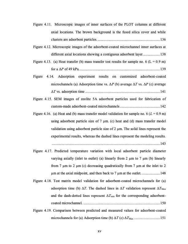
Figure 4.11. Microscopic images of inner surfaces of the PLOT columns at different axial locations. The brown background is the fused silica cover and while clusters are adsorbent particles. .................................................................136 Figure 4.12. Microscopic images of the adsorbent-coated microchannel inner surfaces at different axial locations showing a contiguous adsorbent layer..................138 Figure 4.13. (a) Heat transfer (b) mass transfer test results for sample no. 6 (L = 0.9 m) for a ΔP of 49 kPa.....................................................................................139 Figure 4.14. Adsorption experiment results on customized adsorbent-coated microchannels (a) Adsorption time vs. ΔP (b) average ΔT vs. ΔP (c) average ΔT vs. adsorption time ..............................................................................141 Figure 4.15. SEM images of zeolite 5A adsorbent particles used for fabrication of custom-made adsorbent-coated microchannels..........................................142 Figure 4.16. (a) Heat and (b) mass transfer model validation for sample no. 6 (L = 0.9 m) using adsorbent particle size of 7 μm. (c) heat and (d) mass transfer model validation using adsorbent particle size of 2 μm. The solid lines represent the experimental results, whereas the dashed lines represent the modeling results. .................................................................................................................143 Figure 4.17. Predicted temperature variation with local adsorbent particle diameter varying axially (inlet to outlet) (a) linearly from 2 μm to 7 μm (b) linearly from 7 μm to 2 μm (c) decreasing quadratically from 7 μm at the inlet to 2 μm at the axial midpoint, and then back to 7 μm at the outlet. ...................148 Figure 4.18. Test matrix model validation for adsorbent-coated microchannels for (a) adsorption time (b) ΔT. The dashed lines in ΔT validation represent ΔTMax and the dash-dotted lines represent ΔTmin for the corresponding adsorbent- coated microchannel. ................................................................................150 Figure 4.19. Comparison between predicted and measured values for adsorbent-coated microchannels for (a) Adsorption time (b) ΔT (c) ΔTMax ...........................151 xvPDF Image | TEMPERATURE SWING ADSORPTION PROCESSES FOR GAS SEPARATION

PDF Search Title:
TEMPERATURE SWING ADSORPTION PROCESSES FOR GAS SEPARATIONOriginal File Name Searched:
PAHINKAR-DISSERTATION-2016.pdfDIY PDF Search: Google It | Yahoo | Bing
CO2 Organic Rankine Cycle Experimenter Platform The supercritical CO2 phase change system is both a heat pump and organic rankine cycle which can be used for those purposes and as a supercritical extractor for advanced subcritical and supercritical extraction technology. Uses include producing nanoparticles, precious metal CO2 extraction, lithium battery recycling, and other applications... More Info
Heat Pumps CO2 ORC Heat Pump System Platform More Info
| CONTACT TEL: 608-238-6001 Email: greg@infinityturbine.com | RSS | AMP |