PDF Publication Title:
Text from PDF Page: 008
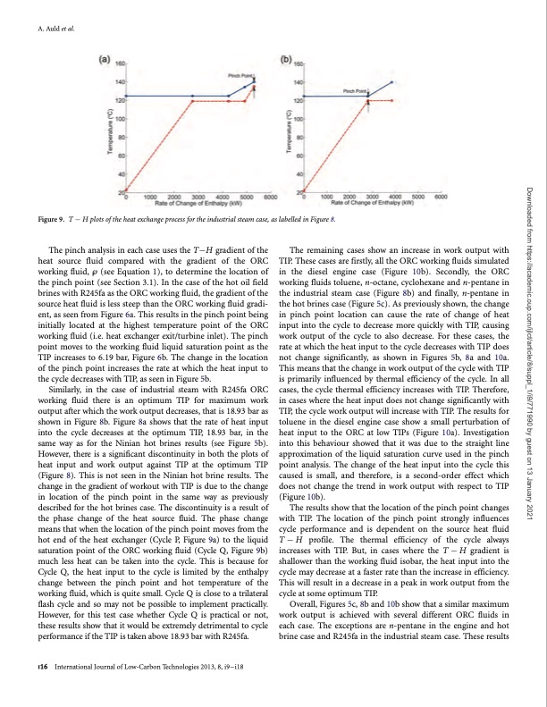
A. Auld et al. Figure9. THplotsoftheheatexchangeprocessfortheindustrialsteamcase,aslabelledinFigure8. The pinch analysis in each case uses the TH gradient of the heat source fluid compared with the gradient of the ORC working fluid, ‘ (see Equation 1), to determine the location of the pinch point (see Section 3.1). In the case of the hot oil field brines with R245fa as the ORC working fluid, the gradient of the source heat fluid is less steep than the ORC working fluid gradi- ent, as seen from Figure 6a. This results in the pinch point being initially located at the highest temperature point of the ORC working fluid (i.e. heat exchanger exit/turbine inlet). The pinch point moves to the working fluid liquid saturation point as the TIP increases to 6.19 bar, Figure 6b. The change in the location of the pinch point increases the rate at which the heat input to the cycle decreases with TIP, as seen in Figure 5b. Similarly, in the case of industrial steam with R245fa ORC working fluid there is an optimum TIP for maximum work output after which the work output decreases, that is 18.93 bar as shown in Figure 8b. Figure 8a shows that the rate of heat input into the cycle decreases at the optimum TIP, 18.93 bar, in the same way as for the Ninian hot brines results (see Figure 5b). However, there is a significant discontinuity in both the plots of heat input and work output against TIP at the optimum TIP (Figure 8). This is not seen in the Ninian hot brine results. The change in the gradient of workout with TIP is due to the change in location of the pinch point in the same way as previously described for the hot brines case. The discontinuity is a result of the phase change of the heat source fluid. The phase change means that when the location of the pinch point moves from the hot end of the heat exchanger (Cycle P, Figure 9a) to the liquid saturation point of the ORC working fluid (Cycle Q, Figure 9b) much less heat can be taken into the cycle. This is because for Cycle Q, the heat input to the cycle is limited by the enthalpy change between the pinch point and hot temperature of the working fluid, which is quite small. Cycle Q is close to a trilateral flash cycle and so may not be possible to implement practically. However, for this test case whether Cycle Q is practical or not, these results show that it would be extremely detrimental to cycle performance if the TIP is taken above 18.93 bar with R245fa. The remaining cases show an increase in work output with TIP. These cases are firstly, all the ORC working fluids simulated in the diesel engine case (Figure 10b). Secondly, the ORC working fluids toluene, n-octane, cyclohexane and n-pentane in the industrial steam case (Figure 8b) and finally, n-pentane in the hot brines case (Figure 5c). As previously shown, the change in pinch point location can cause the rate of change of heat input into the cycle to decrease more quickly with TIP, causing work output of the cycle to also decrease. For these cases, the rate at which the heat input to the cycle decreases with TIP does not change significantly, as shown in Figures 5b, 8a and 10a. This means that the change in work output of the cycle with TIP is primarily influenced by thermal efficiency of the cycle. In all cases, the cycle thermal efficiency increases with TIP. Therefore, in cases where the heat input does not change significantly with TIP, the cycle work output will increase with TIP. The results for toluene in the diesel engine case show a small perturbation of heat input to the ORC at low TIPs (Figure 10a). Investigation into this behaviour showed that it was due to the straight line approximation of the liquid saturation curve used in the pinch point analysis. The change of the heat input into the cycle this caused is small, and therefore, is a second-order effect which does not change the trend in work output with respect to TIP (Figure 10b). The results show that the location of the pinch point changes with TIP. The location of the pinch point strongly influences cycle performance and is dependent on the source heat fluid T H profile. The thermal efficiency of the cycle always increases with TIP. But, in cases where the T H gradient is shallower than the working fluid isobar, the heat input into the cycle may decrease at a faster rate than the increase in efficiency. This will result in a decrease in a peak in work output from the cycle at some optimum TIP. Overall, Figures 5c, 8b and 10b show that a similar maximum work output is achieved with several different ORC fluids in each case. The exceptions are n-pentane in the engine and hot brine case and R245fa in the industrial steam case. These results i16 International Journal of Low-Carbon Technologies 2013, 8, i9–i18 Downloaded from https://academic.oup.com/ijlct/article/8/suppl_1/i9/771990 by guest on 13 January 2021PDF Image | Organic Rankine cycles in waste heat recovery
PDF Search Title:
Organic Rankine cycles in waste heat recoveryOriginal File Name Searched:
ctt033.pdfDIY PDF Search: Google It | Yahoo | Bing
NFT (Non Fungible Token): Buy our tech, design, development or system NFT and become part of our tech NFT network... More Info
IT XR Project Redstone NFT Available for Sale: NFT for high tech turbine design with one part 3D printed counter-rotating energy turbine. Be part of the future with this NFT. Can be bought and sold but only one design NFT exists. Royalties go to the developer (Infinity) to keep enhancing design and applications... More Info
Infinity Turbine IT XR Project Redstone Design: NFT for sale... NFT for high tech turbine design with one part 3D printed counter-rotating energy turbine. Includes all rights to this turbine design, including license for Fluid Handling Block I and II for the turbine assembly and housing. The NFT includes the blueprints (cad/cam), revenue streams, and all future development of the IT XR Project Redstone... More Info
Infinity Turbine ROT Radial Outflow Turbine 24 Design and Worldwide Rights: NFT for sale... NFT for the ROT 24 energy turbine. Be part of the future with this NFT. This design can be bought and sold but only one design NFT exists. You may manufacture the unit, or get the revenues from its sale from Infinity Turbine. Royalties go to the developer (Infinity) to keep enhancing design and applications... More Info
Infinity Supercritical CO2 10 Liter Extractor Design and Worldwide Rights: The Infinity Supercritical 10L CO2 extractor is for botanical oil extraction, which is rich in terpenes and can produce shelf ready full spectrum oil. With over 5 years of development, this industry leader mature extractor machine has been sold since 2015 and is part of many profitable businesses. The process can also be used for electrowinning, e-waste recycling, and lithium battery recycling, gold mining electronic wastes, precious metals. CO2 can also be used in a reverse fuel cell with nafion to make a gas-to-liquids fuel, such as methanol, ethanol and butanol or ethylene. Supercritical CO2 has also been used for treating nafion to make it more effective catalyst. This NFT is for the purchase of worldwide rights which includes the design. More Info
NFT (Non Fungible Token): Buy our tech, design, development or system NFT and become part of our tech NFT network... More Info
Infinity Turbine Products: Special for this month, any plans are $10,000 for complete Cad/Cam blueprints. License is for one build. Try before you buy a production license. May pay by Bitcoin or other Crypto. Products Page... More Info
| CONTACT TEL: 608-238-6001 Email: greg@infinityturbine.com | RSS | AMP |