PDF Publication Title:
Text from PDF Page: 005
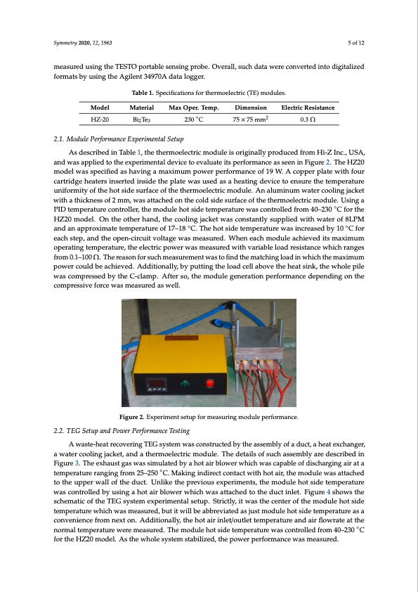
Symmetry 2020, 12, 1963 5 of 12 measured using the TESTO portable sensing probe. Overall, such data were converted into digitalized 5 of 12 As described in Table 1, the thermoelectric module is originally produced from Hi-Z Inc., USA, As described in Table 1, the thermoelectric module is originally produced from Hi-Z Inc., USA, and was applied to the experimental device to evaluate its performance as seen in Figure 2. The HZ20 and was applied to the experimental device to evaluate its performance as seen in Figure 2. The HZ20 formats by using the Agilent 34970A data logger. Symmetry 2020, 12, x FOR PEER REVIEW Table 1. Specifications for thermoelectric (TE) modules. Table 1. Specifications for thermoelectric (TE) modules. Model Material Max Oper. Temp. Dimension Electric Resistance Model Material Max Oper. Temp. Dimension Electric Resistance HZ-20 BiTe 230◦C 75×75m2m2 0.3Ω 23 HZ-20 Bi2Te3 230 °C 75 × 75 mm 0.3 Ω 2.1. Module Performance Experimental Setup 2.1. Module Performance Experimental Setup model was specified as having a maximum power performance of 19 W. A copper plate with four model was specified as having a maximum power performance of 19 W. A copper plate with four cartridge heaters inserted inside the plate was used as a heating device to ensure the temperature cartridge heaters inserted inside the plate was used as a heating device to ensure the temperature uniformity of the hot side surface of the thermoelectric module. An aluminum water cooling jacket uniformity of the hot side surface of the thermoelectric module. An aluminum water cooling jacket with a thickness of 2 mm, was attached on the cold side surface of the thermoelectric module. Using a with a thickness of 2 mm, was attached on the cold side surface of the thermoelectric module. Using PID temperature controller, the module hot side temperature was controlled from 40–230 ◦C for the a PID temperature controller, the module hot side temperature was controlled from 40–230 °C for the HZ20 model. On the other hand, the cooling jacket was constantly supplied with water of 8LPM HZ20 model. On the other hand, the cooling jacket was constantly supplied with water of 8LPM and and an approximate temperature of 17–18 ◦C. The hot side temperature was increased by 10 ◦C for an approximate temperature of 17–18 °C. The hot side temperature was increased by 10 °C for each each step, and the open-circuit voltage was measured. When each module achieved its maximum step, and the open-circuit voltage was measured. When each module achieved its maximum operating temperature, the electric power was measured with variable load resistance which ranges operating temperature, the electric power was measured with variable load resistance which ranges from 0.1–100 Ω. The reason for such measurement was to find the matching load in which the maximum from 0.1–100 Ω. The reason for such measurement was to find the matching load in which the power could be achieved. Additionally, by putting the load cell above the heat sink, the whole pile maximum power could be achieved. Additionally, by putting the load cell above the heat sink, the was compressed by the C-clamp. After so, the module generation performance depending on the whole pile was compressed by the C-clamp. After so, the module generation performance depending compressive force was measured as well. on the compressive force was measured as well. Figure 2. Experiment setup for measuring module performance. 2.2. TEG Setup and Power Performance Testing 2.2. TEG Setup and Power Performance Testing A waste-heat recovering TEG system was constructed by the assembly of a duct, a heat exchanger, A waste-heat recovering TEG system was constructed by the assembly of a duct, a heat a water cooling jacket, and a thermoelectric module. The details of such assembly are described in exchanger, a water cooling jacket, and a thermoelectric module. The details of such assembly are Figure 3. The exhaust gas was simulated by a hot air blower which was capable of discharging air at a described in Figure 3. The exhaust gas was simulated by a hot air blower which was capable of temperature ranging from 25–250 ◦C. Making indirect contact with hot air, the module was attached discharging air at a temperature ranging from 25–250 °C. Making indirect contact with hot air, the to the upper wall of the duct. Unlike the previous experiments, the module hot side temperature module was attached to the upper wall of the duct. Unlike the previous experiments, the module hot was controlled by using a hot air blower which was attached to the duct inlet. Figure 4 shows the side temperature was controlled by using a hot air blower which was attached to the duct inlet. Figure schematic of the TEG system experimental setup. Strictly, it was the center of the module hot side 4 shows the schematic of the TEG system experimental setup. Strictly, it was the center of the module temperature which was measured, but it will be abbreviated as just module hot side temperature as a hot side temperature which was measured, but it will be abbreviated as just module hot side convenience from next on. Additionally, the hot air inlet/outlet temperature and air flowrate at the temperature as a convenience from next on. Additionally, the hot air inlet/outlet temperature and air normal temperature were measured. The module hot side temperature was controlled from 40–230 ◦C flowrate at the normal temperature were measured. The module hot side temperature was controlled for the HZ20 model. As the whole system stabilized, the power performance was measured. from 40–230 °C for the HZ20 model. As the whole system stabilized, the power performance was measured.PDF Image | Small Thermoelectric System Applicable to Real-Time PCR Devices
PDF Search Title:
Small Thermoelectric System Applicable to Real-Time PCR DevicesOriginal File Name Searched:
symmetry-12-01963.pdfDIY PDF Search: Google It | Yahoo | Bing
NFT (Non Fungible Token): Buy our tech, design, development or system NFT and become part of our tech NFT network... More Info
IT XR Project Redstone NFT Available for Sale: NFT for high tech turbine design with one part 3D printed counter-rotating energy turbine. Be part of the future with this NFT. Can be bought and sold but only one design NFT exists. Royalties go to the developer (Infinity) to keep enhancing design and applications... More Info
Infinity Turbine IT XR Project Redstone Design: NFT for sale... NFT for high tech turbine design with one part 3D printed counter-rotating energy turbine. Includes all rights to this turbine design, including license for Fluid Handling Block I and II for the turbine assembly and housing. The NFT includes the blueprints (cad/cam), revenue streams, and all future development of the IT XR Project Redstone... More Info
Infinity Turbine ROT Radial Outflow Turbine 24 Design and Worldwide Rights: NFT for sale... NFT for the ROT 24 energy turbine. Be part of the future with this NFT. This design can be bought and sold but only one design NFT exists. You may manufacture the unit, or get the revenues from its sale from Infinity Turbine. Royalties go to the developer (Infinity) to keep enhancing design and applications... More Info
Infinity Supercritical CO2 10 Liter Extractor Design and Worldwide Rights: The Infinity Supercritical 10L CO2 extractor is for botanical oil extraction, which is rich in terpenes and can produce shelf ready full spectrum oil. With over 5 years of development, this industry leader mature extractor machine has been sold since 2015 and is part of many profitable businesses. The process can also be used for electrowinning, e-waste recycling, and lithium battery recycling, gold mining electronic wastes, precious metals. CO2 can also be used in a reverse fuel cell with nafion to make a gas-to-liquids fuel, such as methanol, ethanol and butanol or ethylene. Supercritical CO2 has also been used for treating nafion to make it more effective catalyst. This NFT is for the purchase of worldwide rights which includes the design. More Info
NFT (Non Fungible Token): Buy our tech, design, development or system NFT and become part of our tech NFT network... More Info
Infinity Turbine Products: Special for this month, any plans are $10,000 for complete Cad/Cam blueprints. License is for one build. Try before you buy a production license. May pay by Bitcoin or other Crypto. Products Page... More Info
| CONTACT TEL: 608-238-6001 Email: greg@infinityturbine.com | RSS | AMP |