PDF Publication Title:
Text from PDF Page: 011
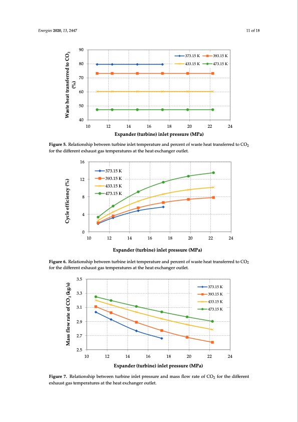
80 70 Energies 2020, 13, 2447 Energies 2020, 13, x FOR PEER REVIEW 373.15 K 433.15 K 373.15 K 433.15 K 393.15 K 473.15 K 393.15 K 473.15 K 11 of 18 60 50 11 of 18 90 40 80 10 12 14 16 18 20 22 24 Expander (turbine) inlet pressure (MPa) 60 Figure 5. Relationship between turbine inlet temperature and percent of waste heat transferred to CO2 for the different exhaust gas temperatures at the heat exchanger outlet. 50 The analysis assumes that waste heat transferred to CO2 is constant for a given exhaust gas 40 70 temperature at the heat exchanger outlet. PWHT is described by Equation (8), where all variables are 10 12 14 16 18 20 22 24 independent of the inlet pressure to the turbine. Figure 5 presents examples of PWHT values for the described above assumptions. Expander (turbine) inlet pressure (MPa) The last energy efficiency indicator is cycle efficiency. The relationship between turbine inlet Figure 5. Relationship between turbine inlet temperature and percent of waste heat transferred to CO2 temperature and cycle efficiency is presented in Figure 6. for the different exhaust gas temperatures at the heat exchanger outlet. Figure 5. Relationship between turbine inlet temperature and percent of waste heat transferred to CO2 for the different exhaust gas temperatures at the heat exchanger outlet. 16 The analysis assumes th3a7t3w.15asKte heat transferred to CO2 is constant for a given exhaust gas temperature at the heat exchanger outlet. PWHT is described by Equation (8), where all variables are independent of the inlet pressure to the turbine. Figure 5 presents examples of PWHT values for the 433.15 K 473.15 K The last energ8y efficiency indicator is cycle efficiency. The relationship between turbine inlet temperature and cycle efficiency is presented in Figure 6. 4 16 FiAgsurtehe6.mRaeslastfiolonwshirpatbeeotwfCeeOn2tuisrbailnseoiannleitmtepmopretaranttupreaaranmdpeetercre,nintoFfigwuarsete7htehaetrtrealnastifoernrsehditpobCeOtween 2 Figure 6. Relationship between turbine inlet temperature and percent of waste heat transferred to CO2 turbfionrethineldeitffperensstuexrehaunsdt gmasastesmflpoewrartuartesoaftCthOe2hiesapt reexscehnantegde.r outlet. 4 3.5 Figure 6 shows that the higher the exhaust gases temperature at the heat exchanger outlet and 0 described above assumptions. 12 393.15 K 373.15 K Energies 2020, 13, x FOR PEER REVIEW393.15 K 0 12 of 18 value with the growth of exhaust gases temperature at the heat exchanger outlet (similar to WHUR), 1210 12 14 16 18 20 22 24 433.15 K 473E.1x5pKander (turbine) inlet pressure (MPa) results from the use of a recuperator, which improves the efficiency of the cycle (Figures 8–10). Mass flow rate of CO2 (kg/s) Cycle efficiency (%) Cycle efficiency (%) Waste heat transferred to CO2 (%) (%) Waste heat transferred to CO 2.5 8 for the different exhaust gas temperatures at the heat exchanger outlet. the higher the turbine inlet pressure, the greater the cycle efficiency. Cycle efficiency refers to the 3.3 393.15 K 10 12 14 16 18 20 22 24 internal efficiency of the system and is independent of the total waste heat amount, which is available 433.15 K in the exhaust gases (with assumption of exhaust gases cooling to 25 °C). The increase in the CE value 3.1 Expander (turbine) inlet pressure (MPa) 473.15 K with the increase of the turbine inlet pressure results from the fact that the higher the turbine inlet pressure, the greater the difference between the power on the turbine shaft and the required 2.9 for the different exhaust gas temperatures at the heat exchanger outlet. 2.7 Figure 6 shows that the higher the exhaust gases temperature at the heat exchanger outlet and the higher the turbine inlet pressure, the greater the cycle efficiency. Cycle efficiency refers to the Figure 6. Relationship between turbine inlet temperature and percent of waste heat transferred to CO2 compressor power. This is due to the compression of CO2 near the critical point. The increase in CE internal efficiency of the system and is independent of the total waste heat amount, which is available 10 12 14 16 18 20 22 24 in the exhaust gases (with assumption of exhaust gases cooling to 25 °C). The increase in the CE value Expander (turbine) inlet pressure (MPa) with the increase of the turbine inlet pressure results from the fact that the higher the turbine inlet pressure, the greater the difference between the power on the turbine shaft and the required Figure 7. Relationship between turbine inlet pressure and mass flow rate of CO2 for the different Figure 7. Relationship between turbine inlet pressure and mass flow rate of CO2 for the different compressor power. This is due to the compression of CO2 near the critical point. The increase in CE exhaust gas temperatures at the heat exchanger outlet. exhaust gas temperatures at the heat exchanger outlet. The CO2 mass flow was not the assumed value. CO2 mass flow was calculated as the required flow so that the given amount of waste heat could be transferred to the S-CO2 system. In the pressure and temperature range assumed for the system operation, the CO2 enthalpy value (for a constant temperature) decreases with increasing pressure. In the case of the discussed system, this is especially 373.15 KPDF Image | Supercritical CO2-Brayton Cycle Nat Gas Compression Station
PDF Search Title:
Supercritical CO2-Brayton Cycle Nat Gas Compression StationOriginal File Name Searched:
energies-13-02447-v2.pdfDIY PDF Search: Google It | Yahoo | Bing
NFT (Non Fungible Token): Buy our tech, design, development or system NFT and become part of our tech NFT network... More Info
IT XR Project Redstone NFT Available for Sale: NFT for high tech turbine design with one part 3D printed counter-rotating energy turbine. Be part of the future with this NFT. Can be bought and sold but only one design NFT exists. Royalties go to the developer (Infinity) to keep enhancing design and applications... More Info
Infinity Turbine IT XR Project Redstone Design: NFT for sale... NFT for high tech turbine design with one part 3D printed counter-rotating energy turbine. Includes all rights to this turbine design, including license for Fluid Handling Block I and II for the turbine assembly and housing. The NFT includes the blueprints (cad/cam), revenue streams, and all future development of the IT XR Project Redstone... More Info
Infinity Turbine ROT Radial Outflow Turbine 24 Design and Worldwide Rights: NFT for sale... NFT for the ROT 24 energy turbine. Be part of the future with this NFT. This design can be bought and sold but only one design NFT exists. You may manufacture the unit, or get the revenues from its sale from Infinity Turbine. Royalties go to the developer (Infinity) to keep enhancing design and applications... More Info
Infinity Supercritical CO2 10 Liter Extractor Design and Worldwide Rights: The Infinity Supercritical 10L CO2 extractor is for botanical oil extraction, which is rich in terpenes and can produce shelf ready full spectrum oil. With over 5 years of development, this industry leader mature extractor machine has been sold since 2015 and is part of many profitable businesses. The process can also be used for electrowinning, e-waste recycling, and lithium battery recycling, gold mining electronic wastes, precious metals. CO2 can also be used in a reverse fuel cell with nafion to make a gas-to-liquids fuel, such as methanol, ethanol and butanol or ethylene. Supercritical CO2 has also been used for treating nafion to make it more effective catalyst. This NFT is for the purchase of worldwide rights which includes the design. More Info
NFT (Non Fungible Token): Buy our tech, design, development or system NFT and become part of our tech NFT network... More Info
Infinity Turbine Products: Special for this month, any plans are $10,000 for complete Cad/Cam blueprints. License is for one build. Try before you buy a production license. May pay by Bitcoin or other Crypto. Products Page... More Info
| CONTACT TEL: 608-238-6001 Email: greg@infinityturbine.com | RSS | AMP |