PDF Publication Title:
Text from PDF Page: 009
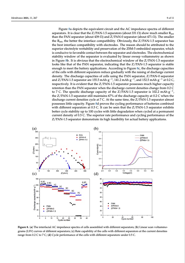
Membranes 2021, 11, x FOR PEER REVIEW 9 of 11 Membranes 2021, 11, 267 9 of 11 Figure 8a depicts the equivalent circuit and the AC impedance spectra of different Figure 8a depicts the equivalent circuit and the AC impedance spectra of different separators. It is clear that the Z/PAN-1.5 separators (about 331 Ω) show much smaller Rint separators. It is clear that the Z/PAN-1.5 separators (about 331 Ω) show much smaller Rint ththaannththeePPAANNseseppaararatotorr(a(baboouutt434939ΩΩ))ananddZZ//PAN-0-0sseeppaararatotorr(a(abboouutt447711ΩΩ).).TThheessmaallelerr ththeeRint, the bettterttheeininteterrfafacceeccoommppaatitbibililtiyty. .OObvbivoiuosulsyl,yt,hteheZ/ZP/APNA-N1.-51.s5epseapratroartohrashtahse int thbesbteinsteirnftaecrefaccoemcpoamtipbailtitbyilwityithweiltehcetrloecdterso.dTehse. Trehaesorneashoonusldhobueldatbtreibautteridbutotetdhetosuthpe- sruiporereiloercetrloeclytrtoelywtetwtaebtitlaitbyilaitnydanpdrepserersveartvioantionfothfethZeSZMS-M5-e5mebmebdeddededsespeaprartaotro,rw,whihcihchis iscocnondduucicviveetotofafavvoorraabbleleccoonttaccttbettween the separator and electtrodeess..Theeelleeccttrroocchheemicicaal l ssttaabbiillitityywiindowoftheseparatorisevalluattedbyylilnineeaarrsswweeeppvvooltlatmammetertyryasashsohwownnin inFiFgiugruer8eb8.bIt.iIstoisbvoibovuisouthsathtahtetehlecetlreoccthroecmhiecmaliwcailnwdoinwdowfthoefZth/PeAZN/P-1A.5Ns-e1p.5arsaetpoarrlaotokrs loliokkesthliakteotfhtahteoPfAthNe sPeApNarasteopra,riantdoirc,aitnindgictahtiantgthtehaZt/PthAeNZ-/1.P5AsNep-1a.r5atsoerpiasrsataobrleisesntoabulgeh enough to meet the battery applications. According to Figure 8c, the discharge capacities to meet the battery applications. According to Figure 8c, the discharge capacities of the of the cells with different separators reduce gradually with the raising of discharge current cells with different separators reduce gradually with the raising of discharge current den- density. The discharge capacities of cells using the PAN separator, Z/PAN-0 separator sity. The discharge capacities of cells using the PAN separator, Z/PAN-0 separator and and Z/PAN-1.5 separator are 155.5 mA−h1 ·g−1, 141.2 mA−1h·g−1, and 152.5 m−1Ah·g−1 at 0.2 C, Z/PAN-1.5 separator are 155.5 mAh·g , 141.2 mAh·g , and 152.5 mAh·g at 0.2 C, respec- respectively. It is evident that the Z/PAN-1.5 separator possesses much higher capacity tively. It is evident that the Z/PAN-1.5 separator possesses much higher capacity retention retention than the PAN separator when the discharge current densities change from 0.2 C than the PAN separator when the discharge current densities change from 0.2 C to 7 C. to 7 C. The specific discharge capacity of the Z/PAN-1.5 separator is 102−1.2 mAh·g−1, The specific discharge capacity of the Z/PAN-1.5 separator is 102.2 mAh·g , the Z/PAN- the Z/PAN-1.5 separator still maintains 67% of the discharge capacity at 0.2 C when the 1.5 separator still maintains 67% of the discharge capacity at 0.2 C when the discharge discharge current densities cycle at 7 C. At the same time, the Z/PAN-1.5 separator almost current densities cycle at 7 C. At the same time, the Z/PAN-1.5 separator almost possesses possesses little capacity. Figure 8d proves the cycling performance of batteries combined little capacity. Figure 8d proves the cycling performance of batteries combined with dif- with different separators at 0.5 C. It can be seen that the Z/PAN-1.5 separator exhibits ferent separators at 0.5 C. It can be seen that the Z/PAN-1.5 separator exhibits better cycle better cycle stability up to 100 cycles with little degradation when cycled at a permanent stability up to 100 cycles with little degradation when cycled at a permanent current den- current density of 0.5 C. The superior rate performance and cycling performance of the sity of 0.5 C. The superior rate performance and cycling performance of the Z/PAN-1.5 Z/PAN-1.5 separator demonstrate its high feasibility for actual battery applications. separator demonstrate its high feasibility for actual battery applications. Figure 8. (a) The interfacial AC impedance spectra of cells assembled with different separators; (b) Linear scan voltammo- Figure 8. (a) The interfacial AC impedance spectra of cells assembled with different separators; (b) Linear scan voltammograms (LSVg)rcaumrvse(LsSoVfd)icfuferrvenstosfedpiafrfearteonrst;s(ecp)aRrateorcsa;p(ac)bRiliattyeocfatphaebcileitllysowfitthedcieffllesrewnithsedpiaffrearteonrtssaetptahreactoursreanttthdencsuirtriesntradnegnesiftrioesm0.2 C tor7anCg;e(dfr)oCmyc0l.e2pCertfoo7rmCa;n(dce) Cofytchlepcelrlfsowrmitahndceiffoefrtehnetcselplsarwatitohrsduifnfedrern0t.s5eCpa.rators under 0.5 C.PDF Image | Electrospinning Polyacrylonitrile Separator with Dip-Coating of Zeolite
PDF Search Title:
Electrospinning Polyacrylonitrile Separator with Dip-Coating of ZeoliteOriginal File Name Searched:
membranes-11-00267.pdfDIY PDF Search: Google It | Yahoo | Bing
CO2 Organic Rankine Cycle Experimenter Platform The supercritical CO2 phase change system is both a heat pump and organic rankine cycle which can be used for those purposes and as a supercritical extractor for advanced subcritical and supercritical extraction technology. Uses include producing nanoparticles, precious metal CO2 extraction, lithium battery recycling, and other applications... More Info
Heat Pumps CO2 ORC Heat Pump System Platform More Info
| CONTACT TEL: 608-238-6001 Email: greg@infinityturbine.com | RSS | AMP |