PDF Publication Title:
Text from PDF Page: 002
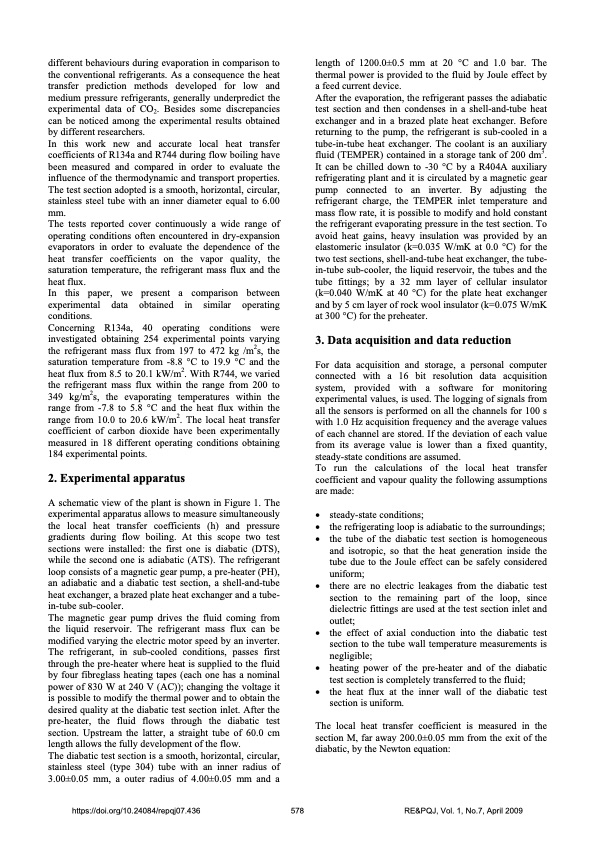
different behaviours during evaporation in comparison to the conventional refrigerants. As a consequence the heat transfer prediction methods developed for low and medium pressure refrigerants, generally underpredict the experimental data of CO2. Besides some discrepancies can be noticed among the experimental results obtained by different researchers. In this work new and accurate local heat transfer coefficients of R134a and R744 during flow boiling have been measured and compared in order to evaluate the influence of the thermodynamic and transport properties. The test section adopted is a smooth, horizontal, circular, stainless steel tube with an inner diameter equal to 6.00 mm. The tests reported cover continuously a wide range of operating conditions often encountered in dry-expansion evaporators in order to evaluate the dependence of the heat transfer coefficients on the vapor quality, the saturation temperature, the refrigerant mass flux and the heat flux. In this paper, we present a comparison between experimental data obtained in similar operating conditions. Concerning R134a, 40 operating conditions were investigated obtaining 254 experimental points varying the refrigerant mass flux from 197 to 472 kg /m2s, the saturation temperature from -8.8 °C to 19.9 °C and the heat flux from 8.5 to 20.1 kW/m2. With R744, we varied the refrigerant mass flux within the range from 200 to 349 kg/m2s, the evaporating temperatures within the range from -7.8 to 5.8 °C and the heat flux within the range from 10.0 to 20.6 kW/m2. The local heat transfer coefficient of carbon dioxide have been experimentally measured in 18 different operating conditions obtaining 184 experimental points. 2. Experimental apparatus A schematic view of the plant is shown in Figure 1. The experimental apparatus allows to measure simultaneously the local heat transfer coefficients (h) and pressure gradients during flow boiling. At this scope two test sections were installed: the first one is diabatic (DTS), while the second one is adiabatic (ATS). The refrigerant loop consists of a magnetic gear pump, a pre-heater (PH), an adiabatic and a diabatic test section, a shell-and-tube heat exchanger, a brazed plate heat exchanger and a tube- in-tube sub-cooler. The magnetic gear pump drives the fluid coming from the liquid reservoir. The refrigerant mass flux can be modified varying the electric motor speed by an inverter. The refrigerant, in sub-cooled conditions, passes first through the pre-heater where heat is supplied to the fluid by four fibreglass heating tapes (each one has a nominal power of 830 W at 240 V (AC)); changing the voltage it is possible to modify the thermal power and to obtain the desired quality at the diabatic test section inlet. After the pre-heater, the fluid flows through the diabatic test section. Upstream the latter, a straight tube of 60.0 cm length allows the fully development of the flow. The diabatic test section is a smooth, horizontal, circular, stainless steel (type 304) tube with an inner radius of 3.00±0.05 mm, a outer radius of 4.00±0.05 mm and a length of 1200.0±0.5 mm at 20 °C and 1.0 bar. The thermal power is provided to the fluid by Joule effect by a feed current device. After the evaporation, the refrigerant passes the adiabatic test section and then condenses in a shell-and-tube heat exchanger and in a brazed plate heat exchanger. Before returning to the pump, the refrigerant is sub-cooled in a tube-in-tube heat exchanger. The coolant is an auxiliary fluid (TEMPER) contained in a storage tank of 200 dm3. It can be chilled down to -30 °C by a R404A auxiliary refrigerating plant and it is circulated by a magnetic gear pump connected to an inverter. By adjusting the refrigerant charge, the TEMPER inlet temperature and mass flow rate, it is possible to modify and hold constant the refrigerant evaporating pressure in the test section. To avoid heat gains, heavy insulation was provided by an elastomeric insulator (k=0.035 W/mK at 0.0 °C) for the two test sections, shell-and-tube heat exchanger, the tube- in-tube sub-cooler, the liquid reservoir, the tubes and the tube fittings; by a 32 mm layer of cellular insulator (k=0.040 W/mK at 40 °C) for the plate heat exchanger and by 5 cm layer of rock wool insulator (k=0.075 W/mK at 300 °C) for the preheater. 3. Data acquisition and data reduction For data acquisition and storage, a personal computer connected with a 16 bit resolution data acquisition system, provided with a software for monitoring experimental values, is used. The logging of signals from all the sensors is performed on all the channels for 100 s with 1.0 Hz acquisition frequency and the average values of each channel are stored. If the deviation of each value from its average value is lower than a fixed quantity, steady-state conditions are assumed. To run the calculations of the local heat transfer coefficient and vapour quality the following assumptions are made: • • • • • • • steady-state conditions; the refrigerating loop is adiabatic to the surroundings; the tube of the diabatic test section is homogeneous and isotropic, so that the heat generation inside the tube due to the Joule effect can be safely considered uniform; there are no electric leakages from the diabatic test section to the remaining part of the loop, since dielectric fittings are used at the test section inlet and outlet; the effect of axial conduction into the diabatic test section to the tube wall temperature measurements is negligible; heating power of the pre-heater and of the diabatic test section is completely transferred to the fluid; the heat flux at the inner wall of the diabatic test section is uniform. https://doi.org/10.24084/repqj07.436 578 RE&PQJ, Vol. 1, No.7, April 2009 The local heat transfer coefficient is measured in the section M, far away 200.0±0.05 mm from the exit of the diabatic, by the Newton equation:PDF Image | Comparison of R744 and R134a
PDF Search Title:
Comparison of R744 and R134aOriginal File Name Searched:
436-mastrullo.pdfDIY PDF Search: Google It | Yahoo | Bing
CO2 Organic Rankine Cycle Experimenter Platform The supercritical CO2 phase change system is both a heat pump and organic rankine cycle which can be used for those purposes and as a supercritical extractor for advanced subcritical and supercritical extraction technology. Uses include producing nanoparticles, precious metal CO2 extraction, lithium battery recycling, and other applications... More Info
Heat Pumps CO2 ORC Heat Pump System Platform More Info
| CONTACT TEL: 608-238-6001 Email: greg@infinityturbine.com | RSS | AMP |