PDF Publication Title:
Text from PDF Page: 007
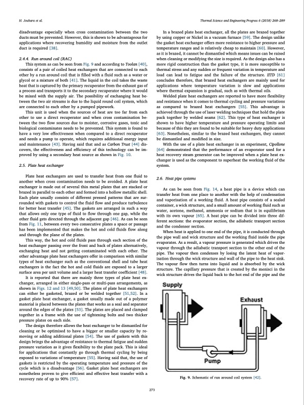
H. Jouhara et al. Thermal Science and Engineering Progress 6 (2018) 268–289 disadvantage especially when cross contamination between the two ducts must be prevented. However, this is shown to be advantageous for applications where recovering humidity and moisture from the outlet duct is required [38]. 2.4.4. Run around coil (RAC) This system as can be seen from Fig. 9 and according to Toolan [40], consists of a pair of coiled heat exchangers that are connected to each other by a run around coil that is filled with a fluid such as a water or glycol or a mixture of both [41]. The liquid in the coil takes the waste heat that is captured by the primary recuperator from the exhaust gas of a process and transports it to the secondary recuperator where it would be mixed with the supply air. The possibility of exchanging heat be- tween the two air streams is due to the liquid round coil system, which are connected to each other by a pumped pipework. This unit is used when the sources of heat are too far from each other to use a direct recuperator and when cross contamination be- tween the two flow sources due to moister, corrosive gases, toxic and biological contaminates needs to be prevented. This system is found to have a very low effectiveness when compared to a direct recuperator and needs a pump to operate, which requires additional energy input and maintenance [43]. Having said that and as Carbon Trust [44] dis- covers, the effectiveness and efficiency of this technology can be im- proved by using a secondary heat source as shown in Fig. 10. 2.5. Plate heat exchanger Plate heat exchangers are used to transfer heat from one fluid to another when cross contamination needs to be avoided. A plate heat exchanger is made out of several thin metal plates that are stacked or brazed in parallel to each other and formed into a hollow metallic shell. Each plate usually consists of different pressed patterns that are sur- rounded with gaskets to control the fluid flow and produce turbulence for better heat transfer [45]. The gaskets are arranged in such a way that allows only one type of fluid to flow through one gap, while the other fluid gets directed through the adjacent gap [46]. As can be seen from Fig. 11, between every two consecutive plates a space or passage has been implemented that makes the hot and cold fluids flow along and through the plane of the plates. This way, the hot and cold fluids pass through each section of the heat exchanger passing over the front and back of plates alternatively, exchanging heat and not getting contaminated with each other. The other advantage plate heat exchangers offer in comparison with similar types of heat exchanger such as the conventional shell and tube heat exchangers is the fact the hot and cold fluids are exposed to a larger surface area per unit volume and a larger heat transfer coefficient [48]. It is reported that there are mainly three types of plate heat ex- changer, arranged in either single-pass or multi-pass arrangements, as shown in Figs. 12 and 13 [49,50]. The plates of plate heat exchangers can either be gasketed, brazed or be welded together [51,52]. In a gasket plate heat exchanger, a gasket usually made out of a polymer material is placed between the plates that works as a seal and separator around the edges of the plates [53]. The plates are placed and clamped together in a frame with the use of tightening bolts and two thicker pressure plates on each side. The design therefore allows the heat exchanger to be dismantled for cleaning or be optimised to have a bigger or smaller capacity by re- moving or adding additional plates [54]. The use of gaskets with this design brings the advantage of resistance to thermal fatigue and sudden pressure variation as it gives flexibility to the plate pack. This is ideal for applications that constantly go through thermal cycling by being exposed to variations of temperature [55]. Having said that, the use of gaskets is restricted by the operating temperature and pressure of the cycle which is a disadvantage [56]. Gasket plate heat exchangers are nonetheless proven to give efficient and effective heat transfer with a recovery rate of up to 90% [57]. In a brazed plate heat exchanger, all the plates are brazed together by using copper or Nickel in a vacuum furnace [59]. The design unlike the gasket heat exchanger offers more resistance to higher pressure and temperature ranges and is relatively cheap to maintain [60]. However, as it is brazed, it cannot be dismantled which means issues can be raised when cleaning or modifying the size is required. As the design also has a more rigid construction than the gasket type, it is more susceptible to thermal stress and any sudden or frequent variation in temperature and load can lead to fatigue and the failure of the structure. IITD [61] concludes therefore, that brazed heat exchangers are mainly used for applications where temperature variation is slow and applications where thermal expansion is gradual, such as with thermal oils. Welded plate heat exchangers are reported to have more flexibility and resistance when it comes to thermal cycling and pressure variations as compared to brazed heat exchangers [55]. This advantage is achieved through the use of laser welding techniques that hold the plate pack together by welded seams [62]. This type of heat exchanger is shown to have higher temperature and pressure operating limits and because of this they are found to be suitable for heavy duty applications [63]. Nonetheless, similar to the brazed heat exchangers, they cannot be dismantled and modified in size. With the use of a plate heat exchanger in an experiment, Cipollone [64] demonstrated that the performance of an evaporator used for a heat recovery steam generator can be improved when a plate heat ex- changer is used as the component to superheat the working fluid of the system. 2.6. Heat pipe systems As can be seen from Fig. 14, a heat pipe is a device which can transfer heat from one place to another with the help of condensation and vaporisation of a working fluid. A heat pipe consists of a sealed container, a wick structure, and a small amount of working fluid such as water, acetone, methanol, ammonia or sodium that is in equilibrium with its own vapour [65]. A heat pipe can be divided into three dif- ferent sections: the evaporator section, the adiabatic transport section and the condenser section. When heat is applied to one end of the pipe, it is conducted through the pipe wall and wick structure and the working fluid inside the pipe evaporates. As a result, a vapour pressure is generated which drives the vapour through the adiabatic transport section to the other end of the pipe. The vapour then condenses by losing the latent heat of vapor- isation through the wick structure and wall of the pipe to the heat sink. The vapour flow then turns into liquid and is absorbed by the wick structure. The capillary pressure that is created by the menisci in the wick structure drives the liquid back to the hot end of the pipe and the Fig. 9. Schematic of run around coil system [42]. 273PDF Image | Waste Heat Recovery Technologies and Applications
PDF Search Title:
Waste Heat Recovery Technologies and ApplicationsOriginal File Name Searched:
1-s20-S2451904918300015-main.pdfDIY PDF Search: Google It | Yahoo | Bing
NFT (Non Fungible Token): Buy our tech, design, development or system NFT and become part of our tech NFT network... More Info
IT XR Project Redstone NFT Available for Sale: NFT for high tech turbine design with one part 3D printed counter-rotating energy turbine. Be part of the future with this NFT. Can be bought and sold but only one design NFT exists. Royalties go to the developer (Infinity) to keep enhancing design and applications... More Info
Infinity Turbine IT XR Project Redstone Design: NFT for sale... NFT for high tech turbine design with one part 3D printed counter-rotating energy turbine. Includes all rights to this turbine design, including license for Fluid Handling Block I and II for the turbine assembly and housing. The NFT includes the blueprints (cad/cam), revenue streams, and all future development of the IT XR Project Redstone... More Info
Infinity Turbine ROT Radial Outflow Turbine 24 Design and Worldwide Rights: NFT for sale... NFT for the ROT 24 energy turbine. Be part of the future with this NFT. This design can be bought and sold but only one design NFT exists. You may manufacture the unit, or get the revenues from its sale from Infinity Turbine. Royalties go to the developer (Infinity) to keep enhancing design and applications... More Info
Infinity Supercritical CO2 10 Liter Extractor Design and Worldwide Rights: The Infinity Supercritical 10L CO2 extractor is for botanical oil extraction, which is rich in terpenes and can produce shelf ready full spectrum oil. With over 5 years of development, this industry leader mature extractor machine has been sold since 2015 and is part of many profitable businesses. The process can also be used for electrowinning, e-waste recycling, and lithium battery recycling, gold mining electronic wastes, precious metals. CO2 can also be used in a reverse fuel cell with nafion to make a gas-to-liquids fuel, such as methanol, ethanol and butanol or ethylene. Supercritical CO2 has also been used for treating nafion to make it more effective catalyst. This NFT is for the purchase of worldwide rights which includes the design. More Info
NFT (Non Fungible Token): Buy our tech, design, development or system NFT and become part of our tech NFT network... More Info
Infinity Turbine Products: Special for this month, any plans are $10,000 for complete Cad/Cam blueprints. License is for one build. Try before you buy a production license. May pay by Bitcoin or other Crypto. Products Page... More Info
| CONTACT TEL: 608-238-6001 Email: greg@infinityturbine.com | RSS | AMP |