PDF Publication Title:
Text from PDF Page: 009
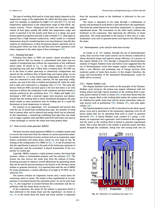
H. Jouhara et al. Thermal Science and Engineering Progress 6 (2018) 268–289 The type of working fluid used in a heat pipe largely depends on the temperature range of the application for which the heat pipe is being used. For example, as explained by Faghri [65] and ACT [74], for low temperature applications in the temperature range of 200–550 K, am- monia, acetone, “Freon” refrigerants and water are used. Most appli- cations of heat pipes usually fall within this temperature range and water is reported to be the mostly used fluid as it is cheap, has good thermo-physical properties and also is safe to handle [75]. Heat pipes in general have a high thermal conductivity, which results in a minimal temperature drop for transferring heat over long distances, long life that requires no maintenance, as they incorporate passive operation and no moving parts which can wear out and they have lower operation costs when compared to the other types of heat exchangers [76]. 2.6.1. Pulsating heat pipes Pulsating heat pipes or PHPs are passive closed two-phase heat transfer devices that are similar to conventional heat pipes and are capable of transporting heat without the requirement of any additional power input. As shown in Fig. 16, the system consists of a narrow meandering long tube that is filled with a working fluid. The PHP can be in the form of either open-loop or closed-loop configuration and operate by the oscillatory flow of liquid slugs and vapour plugs. As can be seen from Fig. 16, in the closed-loop configuration, both ends of the tube are connected to each other, whereas, for the open-loop config- uration, one end of the tube is welded and pinched off, while the other end is open and connected to a charging valve [77,78]. The main dif- ference between PHPs and heat pipes is the fact that there is no wick structure to deliver the condensate to the condenser and heat transfer is entirely achieved by the oscillatory flow [79]. Holley and Faghri [80] developed a PHP with a sintered copper wick structure and demon- strated that the working fluid is better distributed throughout the pipe which results in more nucleation sites for boiling and as a result the fluctuation in local temperature is reduced. For instance in an experiment, [82] investigated and proved that with the use of closed-loop oscillating heat pipe, the quantity of using fuel in pottery kilns can be reduced and energy thrift can be achieved. In this experiment, a closed-loop oscillating heat pipe that was made out of copper capillary tube and filled with R123 and water was used as a heat exchanger to recover the waste heat from pottery kilns. 2.7. Heat recovery steam generator (HRSG) The heat recovery steam generator (HRSG) is a complex system used to recover the waste heat from the exhaust of a power generation plant. It consists of several heat recovery sections such as an evaporator, super heater, economiser and steam drum, which are very large in size. By looking at the configuration of a HRSG in Fig. 17, it can be pointed out that the superheater is placed in the path of the hottest gas upstream of the evaporator and the economiser is placed downstream of the eva- porator in coolest gas. Typically, HRSGs comprise a triple pressure system, this being high pressure, reheat or intermediate pressure and low pressure [84]. The system can also recover the waste heat from the exhaust of manu- facturing processes to improve overall efficiencies by generating steam that can be used for process heating in the factory or for driving a steam turbine to generate electricity. It is reported that with the use of HRSG for steam production, a system efficiency of as high as 75–85% can be achieved [85]. The system contains an evaporator section and a steam drum for converting water to steam. The steam is then superheated as its tem- perature is increased beyond the saturation point. As can be seen from Fig. 18, the evaporator is located between the economiser and the su- perheater with the steam drum on top of it. In the evaporator, the steam for the turbine is generated which is then delivered to the steam drum and the superheater. As shown in Fig. 18, in the steam drum the steam and water mixture is separated from the saturated steam as the feedwater is delivered to the eva- porator. The steam is separated in two steps through a combination of gravity and mechanical work before it gets delivered to the superheater. This heats the steam beyond the saturation temperature, i.e. generating superheated steam. The economiser on the other hand, preheats the feedwater to the evaporator, thus improving the efficiency of steam generation. The steam generated in the process is then sent to a ther- modynamic cycle such to generate power and improve the efficiency of the plant. 2.8. Thermodynamic cycles used for waste heat recovery As Costiuc et al. [87] explain, through the use of thermodynamic cycles, heat recovery from waste sources can be directly conducted to obtain electrical energy and improve energy efficiency of a process. In this regard, Nemati et al. [88] through a comparative thermodynamic analysis of Organic Rankine Cycle and Kalina Cycle suggested that the use of thermodynamic cycles that employ organic working fluids en- ables a cost effective and promising way of energy recovery from moderate grades of waste heat sources. In this chapter therefore, the usage and functionality of the mentioned thermodynamic cycles for WHR will be reviewed. 2.8.1. Organic Rankine cycle The Organic Rankine Cycle works on the principle of the Clausius- Rankine cycle, however, the system uses organic substances with low boiling points and high vapour pressures as the working fluid to gen- erate power instead of water or steam [89]. It has been shown that the use of an organic fluid as the working fluid makes the system suitable for utilising low grade waste heat and for power generation using en- ergy sources such as geothermal [90], biomass [91], and solar appli- cations [92]. The Clausius-Rankine Cycle or CRC is introduced as the ideal vapour power cycle and is described as the elementary operating cycle for all power plants that use an operating fluid such as water to generate electricity [93]. A typical Rankine cycle consists of a pump, a con- denser, an evaporator and a generator. Fuel is burned in the evaporator and the water as the working fluid is heated to generate superheated steam. This is then directed to the turbine to generate power and then passed through the condenser, losing heat and turning back into its Fig. 16. Schematic of a pulsating heat pipe [81]. 275PDF Image | Waste Heat Recovery Technologies and Applications
PDF Search Title:
Waste Heat Recovery Technologies and ApplicationsOriginal File Name Searched:
1-s20-S2451904918300015-main.pdfDIY PDF Search: Google It | Yahoo | Bing
NFT (Non Fungible Token): Buy our tech, design, development or system NFT and become part of our tech NFT network... More Info
IT XR Project Redstone NFT Available for Sale: NFT for high tech turbine design with one part 3D printed counter-rotating energy turbine. Be part of the future with this NFT. Can be bought and sold but only one design NFT exists. Royalties go to the developer (Infinity) to keep enhancing design and applications... More Info
Infinity Turbine IT XR Project Redstone Design: NFT for sale... NFT for high tech turbine design with one part 3D printed counter-rotating energy turbine. Includes all rights to this turbine design, including license for Fluid Handling Block I and II for the turbine assembly and housing. The NFT includes the blueprints (cad/cam), revenue streams, and all future development of the IT XR Project Redstone... More Info
Infinity Turbine ROT Radial Outflow Turbine 24 Design and Worldwide Rights: NFT for sale... NFT for the ROT 24 energy turbine. Be part of the future with this NFT. This design can be bought and sold but only one design NFT exists. You may manufacture the unit, or get the revenues from its sale from Infinity Turbine. Royalties go to the developer (Infinity) to keep enhancing design and applications... More Info
Infinity Supercritical CO2 10 Liter Extractor Design and Worldwide Rights: The Infinity Supercritical 10L CO2 extractor is for botanical oil extraction, which is rich in terpenes and can produce shelf ready full spectrum oil. With over 5 years of development, this industry leader mature extractor machine has been sold since 2015 and is part of many profitable businesses. The process can also be used for electrowinning, e-waste recycling, and lithium battery recycling, gold mining electronic wastes, precious metals. CO2 can also be used in a reverse fuel cell with nafion to make a gas-to-liquids fuel, such as methanol, ethanol and butanol or ethylene. Supercritical CO2 has also been used for treating nafion to make it more effective catalyst. This NFT is for the purchase of worldwide rights which includes the design. More Info
NFT (Non Fungible Token): Buy our tech, design, development or system NFT and become part of our tech NFT network... More Info
Infinity Turbine Products: Special for this month, any plans are $10,000 for complete Cad/Cam blueprints. License is for one build. Try before you buy a production license. May pay by Bitcoin or other Crypto. Products Page... More Info
| CONTACT TEL: 608-238-6001 Email: greg@infinityturbine.com | RSS | AMP |