PDF Publication Title:
Text from PDF Page: 005
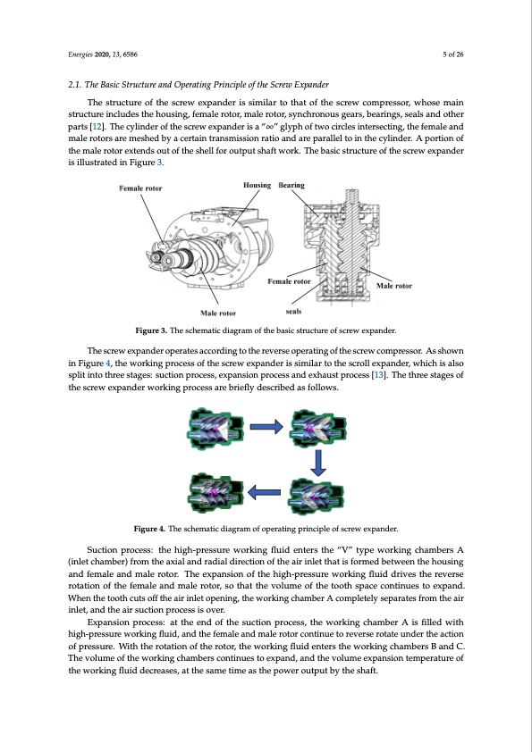
With the rapid rise of geothermal power generation technology in the United States, the screw expander has captured increasing attention due to its ability of full-flow expansion. However, due to the influence of rotor profile and rotor machining precision, the performance of the screw expander has so far failed to meet the requirements. Regarding enhancing the performance of the expansion, the study of the screw expander is concentrated in the following areas: (1) leakage of screw expander, Energies 2020, 13, 6586 5 of 26 (2) rotor profile, (3) processing method and equipment, (4) sealing, (5) thermodynamic model and simulation. 2.1. The Basic Structure and Operating Principle of the Screw Expander 2.1. The Basic Structure and Operating Principle of the Screw Expander The structure of the screw expander is similar to that of the screw compressor, whose main The structure of the screw expander is similar to that of the screw compressor, whose main structure includes the housing, female rotor, male rotor, synchronous gears, bearings, seals and other structure includes the housing, female rotor, male rotor, synchronous gears, bearings, seals and other parts [12]. The cylinder of the screw expander is a “∞” glyph of two circles intersecting, the female and parts [12]. The cylinder of the screw expander is a “∞” glyph of two circles intersecting, the female male rotors are meshed by a certain transmission ratio and are parallel to in the cylinder. A portion of and male rotors are meshed by a certain transmission ratio and are parallel to in the cylinder. A the male rotor extends out of the shell for output shaft work. The basic structure of the screw expander portion of the male rotor extends out of the shell for output shaft work. The basic structure of the is illustrated in Figure 3. screw expander is illustrated in Figure 3. Energies 2020, 13, x FOR PEER REVIEW 6 of 26 Suction process: the high-pressure working fluid enters the “V” type working chambers A (inlet chamber) from the axial and radial direction of the air inlet that is formed between the housing and female and male rotor. The expansion of the high-pressure working fluid drives the reverse rotation of the female and male rotor, so that the volume of the tooth space continues to expand. When the tooth cuts off the air inlet opening, the working chamber A completely separates from the air inlet, and the air suction process is over. Expansion process: at the end of the suction process, the working chamber A is filled with high- pressure working fluid, and the female and male rotor continue to reverse rotate under the action of Figure 3. The schematic diagram of the basic structure of screw expander. Figure 3. The schematic diagram of the basic structure of screw expander. pressure. With the rotation of the rotor, the working fluid enters the working chambers B and C. The volumTheeosfcrthewewexopraknindgercohpamerabteersaccocnotridniunegsttoothexepreavnedr,saenodpethraetivnogluomftheesxcpraenwscionmtpermespseora.tAurseshoofwthne The screw expander operates according to the reverse operating of the screw compressor. As iwnoFrikgiunrgef4l,utihdedwecorekaisnegs,partotcheesssaomf tehetimscereaws tehxeppanodweerrisousitmpuiltabrytoththeeshscarfot.ll expander, which is also shown in Figure 4, the working process of the screw expander is similar to the scroll expander, which split iEnxtohathursetepsrtoacgeess:: swuictthiotnheprotcoerssr,oetaxtpianngs,itohnepwrocrkesinsganflduiedxheanutesrtsptrhoecewssor[k13in].gTcheamthbreer Dsta. Wgehseonf is also split into three stages: suction process, expansion process and exhaust process [13]. The three tDheiscroenwnecxtpedantdoetrhwe eoxrkhianugstpprocret,ssthaerexbhriaeuflsyt pdreoscreisbsebdeagsinfso.llWowhes.n the volume of D goes down to stages of the screw expander working process are briefly described as follows. zero, this work cycle ends. Figure 4. The schematic diagram of operating principle of screw expander. Figure 4. The schematic diagram of operating principle of screw expander. Suction process: the high-pressure working fluid enters the “V” type working chambers A 2.2. Research on Leakage of Screw Expander (inlet chamber) from the axial and radial direction of the air inlet that is formed between the housing For the screw machine, due to many factors such as lubrication and installation accuracy, there and female and male rotor. The expansion of the high-pressure working fluid drives the reverse is always some gap between the rotor and the rotor and between the rotor and the housing. Because rotation of the female and male rotor, so that the volume of the tooth space continues to expand. of this gap, the leakage of the screw expander is inevitable. Leakage clearance size determines the When the tooth cuts off the air inlet opening, the working chamber A completely separates from the air size of the leakage, and the size of the leakage is the most important factor affecting the performance inlet, and the air suction process is over. of the expander. Therefore, many scholars have conducted extensive research on the leakage of the Expansion process: at the end of the suction process, the working chamber A is filled with screw mechanism. high-pressure working fluid, and the female and male rotor continue to reverse rotate under the action of pressure. With the rotation of the rotor, the working fluid enters the working chambers B and C. JanPrins et al. [15] used the method of an experiment to measure the size of the housing sealing line gap that directly related to the rotor profile, and the indicated diagram of leakage gap size was 2.2.1. Research on Screw Mechanical Leakage The volume of the working chambers continues to expand, and the volume expansion temperature of the working fluid decreases, at the same time as the power output by the shaft. Fong et al. [14] proposed a new mathematical procedure for calculating the inter-lobe clearance between two screw rotors, and described the clearance field with the iso-clearance contour diagram (ICCD). The geometrical and kinematical relations of mating rotors were calculated by the theory of gearing and the tooth contact analysis (TCA), and the contact lines and the approximate blowhole were calculated by TCA.PDF Image | Development and Application of the Twin Screw Expander
PDF Search Title:
Development and Application of the Twin Screw ExpanderOriginal File Name Searched:
energies-13-06586.pdfDIY PDF Search: Google It | Yahoo | Bing
NFT (Non Fungible Token): Buy our tech, design, development or system NFT and become part of our tech NFT network... More Info
IT XR Project Redstone NFT Available for Sale: NFT for high tech turbine design with one part 3D printed counter-rotating energy turbine. Be part of the future with this NFT. Can be bought and sold but only one design NFT exists. Royalties go to the developer (Infinity) to keep enhancing design and applications... More Info
Infinity Turbine IT XR Project Redstone Design: NFT for sale... NFT for high tech turbine design with one part 3D printed counter-rotating energy turbine. Includes all rights to this turbine design, including license for Fluid Handling Block I and II for the turbine assembly and housing. The NFT includes the blueprints (cad/cam), revenue streams, and all future development of the IT XR Project Redstone... More Info
Infinity Turbine ROT Radial Outflow Turbine 24 Design and Worldwide Rights: NFT for sale... NFT for the ROT 24 energy turbine. Be part of the future with this NFT. This design can be bought and sold but only one design NFT exists. You may manufacture the unit, or get the revenues from its sale from Infinity Turbine. Royalties go to the developer (Infinity) to keep enhancing design and applications... More Info
Infinity Supercritical CO2 10 Liter Extractor Design and Worldwide Rights: The Infinity Supercritical 10L CO2 extractor is for botanical oil extraction, which is rich in terpenes and can produce shelf ready full spectrum oil. With over 5 years of development, this industry leader mature extractor machine has been sold since 2015 and is part of many profitable businesses. The process can also be used for electrowinning, e-waste recycling, and lithium battery recycling, gold mining electronic wastes, precious metals. CO2 can also be used in a reverse fuel cell with nafion to make a gas-to-liquids fuel, such as methanol, ethanol and butanol or ethylene. Supercritical CO2 has also been used for treating nafion to make it more effective catalyst. This NFT is for the purchase of worldwide rights which includes the design. More Info
NFT (Non Fungible Token): Buy our tech, design, development or system NFT and become part of our tech NFT network... More Info
Infinity Turbine Products: Special for this month, any plans are $10,000 for complete Cad/Cam blueprints. License is for one build. Try before you buy a production license. May pay by Bitcoin or other Crypto. Products Page... More Info
| CONTACT TEL: 608-238-6001 Email: greg@infinityturbine.com | RSS | AMP |