INFINITY TURBINE LLC We specialize in designs, plans, licensing, consulting, design services, and surplus spare parts. We no longer manufacture turbines or CO2 systems. More Info...
TEL: +1-608-238-6001 (Chicago Time Zone ) USA
Email: greg@infinityturbine.com
CO2 Ejectors for Data Center Waste Heat Cooling: A Technical Review Hyperscalers are racing to deploy gigawatts of AI compute, but the grid can't keep up and large gas turbines are backordered half a decade out. Infinity Turbine's Cluster Mesh Supercritical CO₂ system offers a radical alternative: modular, silent, trailer-deployable prime power that scales the way software does... More Info
Turning AI Data Center Waste Heat Into Electricity More Info
Cooling a Data Center Pod with Its Own Waste Heat: A 100 kW Ejector Design Study More Info
Portable Gas Turbine Prime Power AI data centers are pushing electrical infrastructure to its limits. The traditional AC power chain is no longer optimal for GPU-driven workloads. A DC-native architecture using Infinity Turbine’s Cluster Mesh system offers a path to higher efficiency, lower costs, and scalable modular power—potentially saving tens of millions per year at hyperscale... More Info
SMR and Cluster Mesh Supercritical CO2 Power System for Data Centers and AI Pairing Cluster Mesh Supercritical CO2 Power System with Small Modular Reactors enables hyperscalers to convert high-grade nuclear heat into ultra-efficient, dispatchable power with a compact, modular footprint tailored for AI-scale demand. More Info
ORC and Products Index Infinity Turbine ORC Index... More Info
AMD Helios Cooling Strategy Using Transcritical CO2 and a Cluster Mesh sCO2 Turbine Generator Cell More Info
|
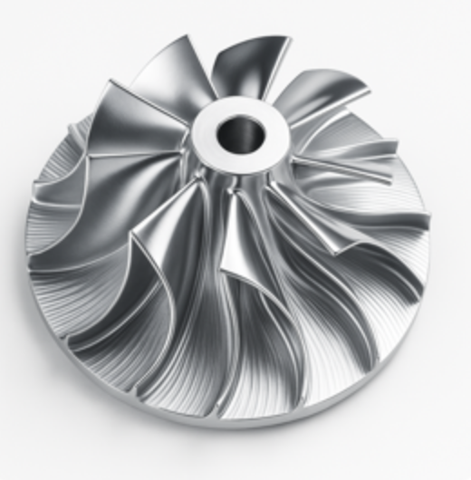
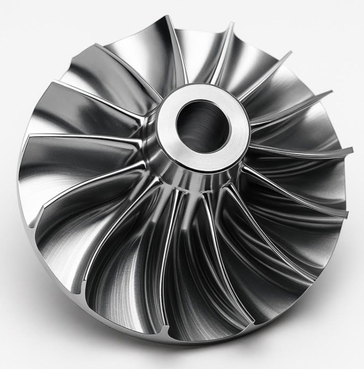
Radial-Inflow Turbine Geometry for Supercritical CO2: From Pressure Ratio and RPM to Bucket Angles and Diameters OverviewFor compact supercritical CO2 systems, a single radial-inflow turbine stage is common. The goal is to convert a specified total-to-static enthalpy drop into shaft work while keeping inlet Mach numbers and incidence under control. With CO2’s dense, non-ideal behavior, you should size to the actual inlet state (pressure, temperature, cp, k, compressibility Z, density) rather than air-based rules.This guide gives a first-cut sizing workflow and a FileMaker Pro calculation that returns the key geometry:Tip speed and tip diameterRotor inlet blade heightInlet absolute and relative metal anglesSanity checks for Mach numberIt assumes a radial-inflow turbine with near-zero exit swirl (a common target), high effectiveness recuperation upstream, and a specified overall pressure ratio across the turbine stage.Design coefficients to chooseThese are typical starting values; adjust during iteration.Turbine isentropic efficiency, eta_t: 0.80 to 0.90Stage loading coefficient, psi_t = delta_h0 over U2^2: 1.0 to 1.6Flow coefficient at rotor inlet, phi_t = Vm2 over U2: 0.15 to 0.25Slip and exit swirl: target Vw3 approx 0 (zero exit swirl)Radius ratio, rr = R3 over R2: 0.35 to 0.50 (sets hub exit diameter)Inlet relative Mach target: Mrel2 less than about 1.2Inputs and CO2 propertiesProvide these as fields or globals in FileMaker. If you do not compute properties in FileMaker, precompute with REFPROP or CoolProp and store them.T3_K turbine inlet total temperature, KP3_Pa turbine inlet total pressure, PaPR_t turbine pressure ratio P3 over P4 (total to static target)N_rpm shaft speed, rpmmdot_kg_s mass flow, kg per scp3_J_kgK cp at inlet, J per kg Kk3 ratio of specific heats at inletZ3 compressibility at inletrho2_kg_m3 CO2 density at rotor inlet plane, kg per m3rho3_kg_m3 CO2 density at rotor exit plane, kg per m3 (first pass use same as inlet, then refine)Design choices as fields or constants:eta_t, psi_t, phi_t, rrFixed constant:R_CO2_J_kgK = 188.9Sizing logic in words1. Isentropic head from pressure ratioHs = cp3 T3 (1 − PR_t^((k3 − 1) over k3))Actual specific work to shaft: delta_h0 = eta_t Hs2. Tip speed and diameterpsi_t = delta_h0 over U2^2 so U2 = sqrt(delta_h0 over psi_t)D2 = 60 U2 over (pi N_rpm)3. Inlet meridional velocity and blade heightVm2 = phi_t U2mdot = rho2 (2 pi R2 b2) Vm2, with R2 = D2 over 2Solve for b24. Inlet velocity triangles and metal anglesWith zero exit swirl, Euler gives Vw2 = delta_h0 over U2Absolute inlet angle alpha2 = atan(Vm2 over Vw2)Relative tangential Wt2 = U2 − Vw2Relative inlet angle beta2 = atan(Vm2 over Wt2)5. Exit diameter from radius ratioD3 = rr D2Use continuity with rho3 to check b3 if you want to size the diffuser and volute later.6. Mach sanity checka2 = sqrt(k3 R_CO2 T3 over Z3)W2 = sqrt( (U2 − Vw2)^2 + Vm2^2 )Mrel2 = W2 over a2FileMaker Pro calculationPaste this into a FileMaker calculation field. Replace field names with your own as needed. It returns a plain text report.```Let([R_CO2 = 188.9;pi = 3.14159265358979;// InputsT3 = T3_K;P3 = P3_Pa;PRt = PR_t;N = N_rpm;mdot = mdot_kg_s;cp = cp3_J_kgK;k = k3;Z = Z3;rho_in = rho2_kg_m3;rho_out = rho3_kg_m3;// Design coefficientseta = eta_t;psi = psi_t;phi = phi_t;rr = rr;// 1) Isentropic head and actual stage work (positive to shaft)Hs = cp T3 ( 1 • Power( PRt, (k • 1) / k ) );dh0 = eta Hs; // actual specific work to shaft, J/kg// 2) Tip speed and tip diameterU2 = Sqrt( dh0 / psi ); // m/sD2 = 60 U2 / ( pi N ); // m// 3) Inlet meridional velocity and blade heightVm2 = phi U2; // m/sb2 = mdot / ( rho_in 2 pi ( D2 / 2 ) Vm2 ); // m// 4) Inlet velocity triangles and metal angles// Zero exit swirl target => Vw3 approx 0, so Euler: dh0 = U2 Vw2Vw2 = dh0 / U2; // m/s absolute tangential at inletWt2 = U2 • Vw2; // m/s relative tangentialalpha2_deg = 57.295779513 Atan( Vm2 / Vw2 ); // absolute metal angle at inletbeta2_deg = 57.295779513 Atan( Vm2 / Wt2 ); // relative metal angle at inlet// 5) Exit diameter from radius ratioD3 = rr D2; // m// Optional: exit blade height from continuity assuming Vm3 approx Vm2Vm3 = Vm2;b3 = mdot / ( rho_out 2 pi ( D3 / 2 ) Vm3 ); // m// 6) Mach check at inlet (relative)a2 = Sqrt( k R_CO2 T3 / Z ); // m/sW2 = Sqrt( Wt2^2 + Vm2^2 ); // m/sMrel2 = W2 / a2];Results & Char(10) &Tip speed U2 m_s = & Round(U2;3) & Char(10) &Rotor tip diameter D2 m = & Round(D2;4) & Char(10) &Rotor inlet blade height b2 m = & Round(b2;4) & Char(10) &Inlet absolute angle alpha2 deg = & Round(alpha2_deg;1) & Char(10) &Inlet relative angle beta2 deg = & Round(beta2_deg;1) & Char(10) &Exit diameter D3 m = & Round(D3;4) & Char(10) &Exit blade height b3 m = & Round(b3;4) & Char(10) &Relative inlet Mach Mrel2 = & Round(Mrel2;2))```Practical guidanceStart with psi_t about 1.2 and phi_t about 0.20 for dense CO2. If Mrel2 is high, reduce pressure ratio per stage, increase D2 slightly, or reduce phi_t.Keep Mrel2 less than about 1.2 at design to avoid strong shocks and loss.If b2 becomes too small to manufacture, increase phi_t modestly or reduce delta_h0 by lowering pressure ratio per stage and use two stages.Recompute rho_in and rho_out using a real gas property model at the rotor planes after you have draft geometry, then iterate.What this solvesGiven T3, P3, pressure ratio, RPM, and mass flow, plus CO2 properties, this first-cut method returns:The tip diameter and blade height that pass the flow at acceptable velocityThe inlet metal angles that set the velocity triangles and incidenceA Mach check for survivable aerodynamicsFrom there, you can detail the nozzle, rotor metal camber and thickness, diffuser and volute, and iterate with real-gas CFD and meanline tools.----Let([R_CO2 = 188.9;pi = 3.14159265358979;// InputsT3 = T3_K;P3 = P3_Pa;PRt = PR_t;N = N_rpm;mdot = mdot_kg_s;cp = cp3_J_kgK;k = k3;Z = Z3;rho_in = rho2_kg_m3;rho_out = rho3_kg_m3;// Design coefficientseta = eta_t;psi = psi_t;phi = phi_t;rr = rr;// 1) Isentropic head and actual stage work (positive to shaft)Hs = cp * T3 * ( 1 - Power( PRt, (k - 1) / k ) );dh0 = eta * Hs; // actual specific work to shaft, J/kg// 2) Tip speed and tip diameterU2 = Sqrt( dh0 / psi ); // m/sD2 = 60 * U2 / ( pi * N ); // m// 3) Inlet meridional velocity and blade heightVm2 = phi * U2; // m/sb2 = mdot / ( rho_in * 2 * pi * ( D2 / 2 ) * Vm2 ); // m// 4) Inlet velocity triangles and metal angles// Zero exit swirl target => Vw3 approx 0, so Euler: dh0 = U2 * Vw2Vw2 = dh0 / U2; // m/s absolute tangential at inletWt2 = U2 - Vw2; // m/s relative tangentialalpha2_deg = 57.295779513 * Atan( Vm2 / Vw2 ); // absolute metal angle at inletbeta2_deg = 57.295779513 * Atan( Vm2 / Wt2 ); // relative metal angle at inlet// 5) Exit diameter from radius ratioD3 = rr * D2; // m// Optional: exit blade height from continuity assuming Vm3 approx Vm2Vm3 = Vm2;b3 = mdot / ( rho_out * 2 * pi * ( D3 / 2 ) * Vm3 ); // m// 6) Mach check at inlet (relative)a2 = Sqrt( k * R_CO2 * T3 / Z ); // m/sW2 = Sqrt( Wt2^2 + Vm2^2 ); // m/sMrel2 = W2 / a2];"Results" & Char(10) &"Tip speed U2 m_s = " & Round(U2;3) & Char(10) &"Rotor tip diameter D2 m = " & Round(D2;4) & Char(10) &"Rotor inlet blade height b2 m = " & Round(b2;4) & Char(10) &"Inlet absolute angle alpha2 deg = " & Round(alpha2_deg;1) & Char(10) &"Inlet relative angle beta2 deg = " & Round(beta2_deg;1) & Char(10) &"Exit diameter D3 m = " & Round(D3;4) & Char(10) &"Exit blade height b3 m = " & Round(b3;4) & Char(10) &"Relative inlet Mach Mrel2 = " & Round(Mrel2;2)) |
|
|
| CONTACT TEL: +1-608-238-6001 (Chicago Time Zone USA) Email: greg@infinityturbine.com | AMP | PDF |