
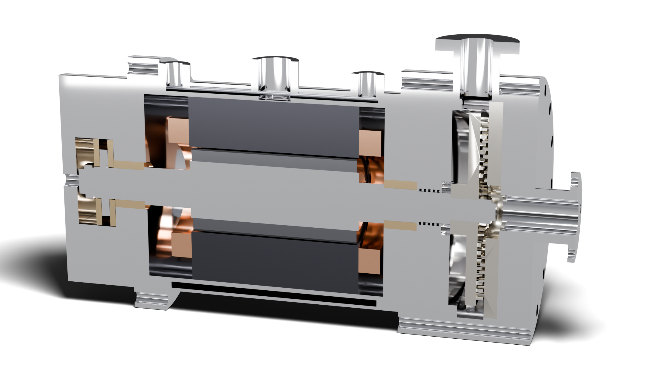
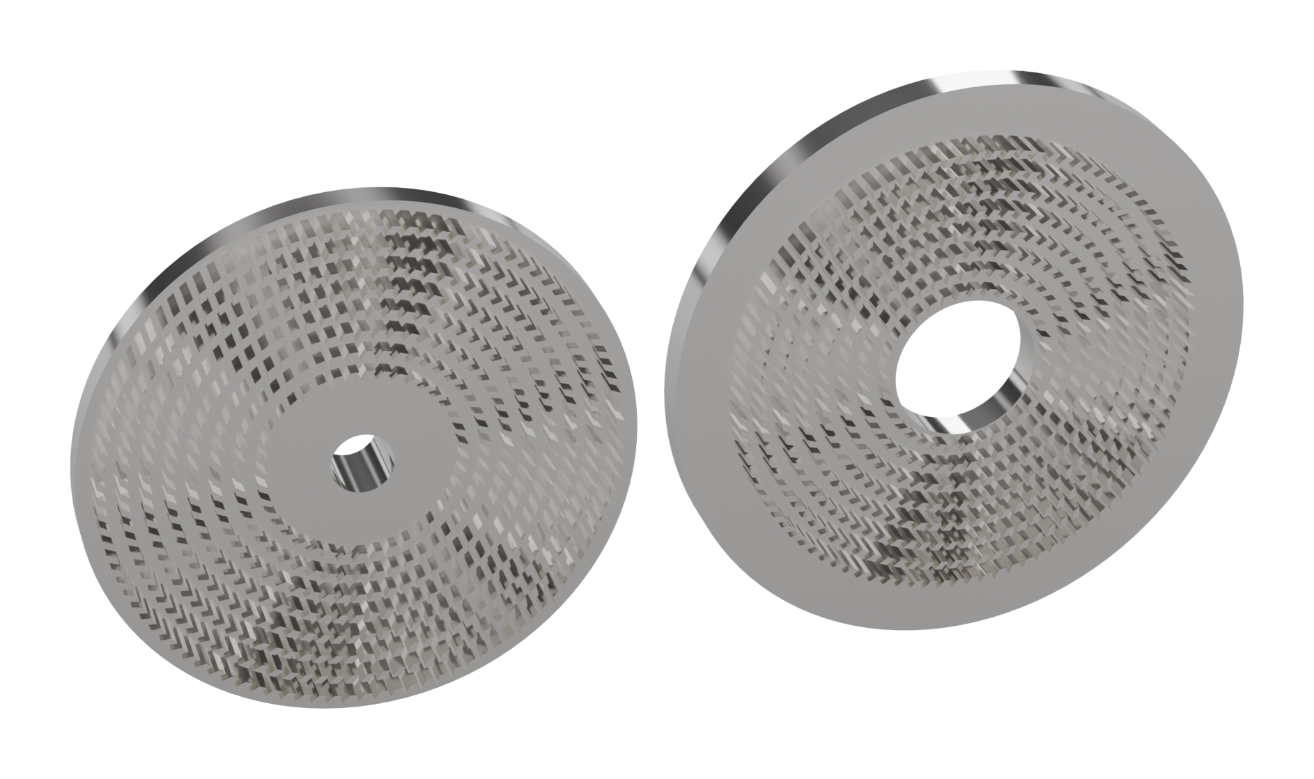
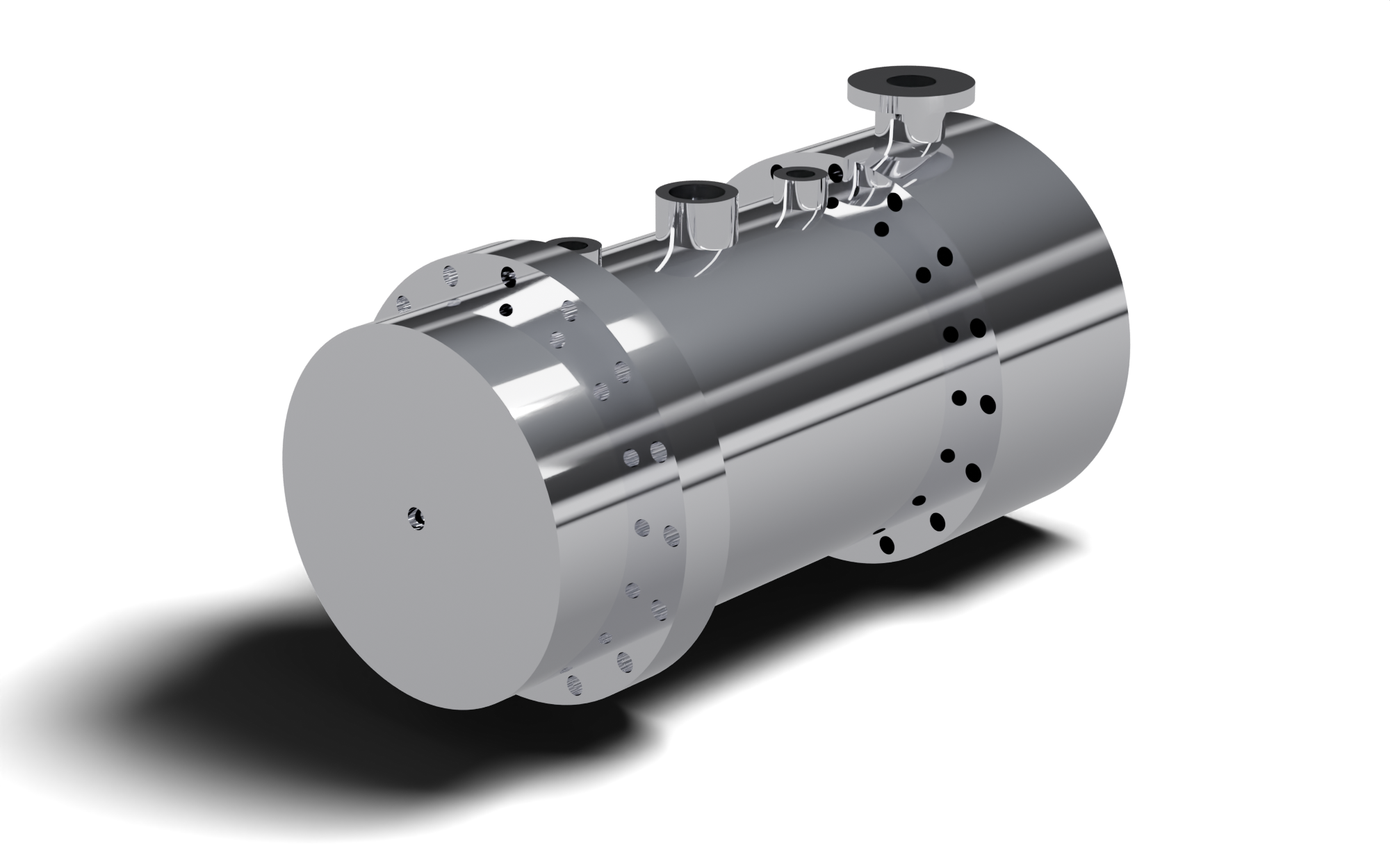
An 8-stage supercritical CO₂ radial outflow turbine and a 55 kW HSG-55R high-speed permanent-magnet generator on one shaft, in one hermetic block. It turns 100–650 °C heat into up to 51 kW of gross electric power, with no gearbox and no shaft seal to atmosphere.
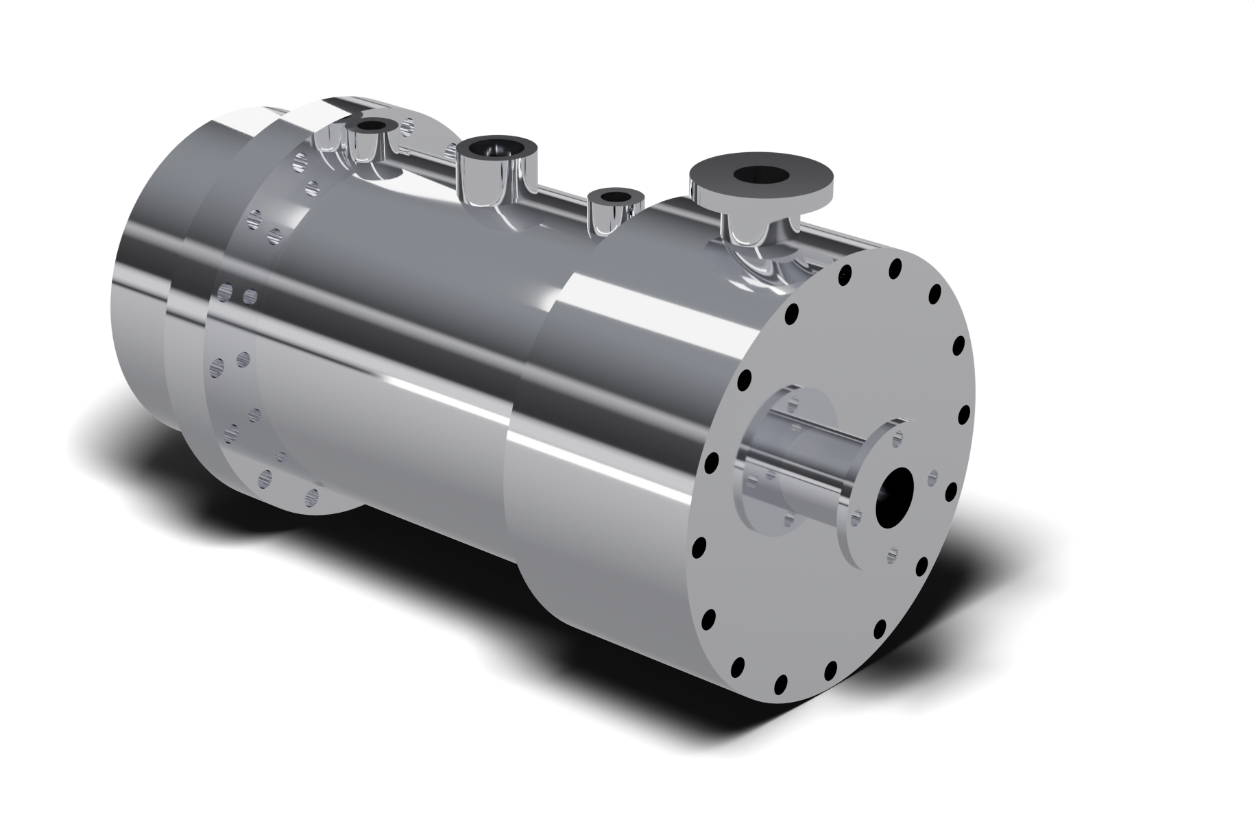
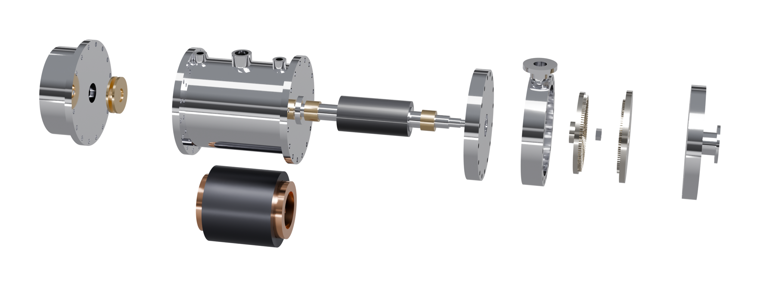
Most turbine plans stop at the rotor and leave you to find a generator that can run at turbine speed. The ROT-8-650 plans include the full HSG-55R generator design: an 11-sheet drawing set plus a build list with prototype cost estimates. The generator rotor is the turbine shaft, so there is no coupling, no gearbox and no rotating seal.
Pick the route that fits your shop, budget and schedule. Every option is based on the same Rev A design package.
Factory-assembled ROT-8-650 with HSG-55R generator, ready to connect to your CO₂ loop and inverter.
All the major parts of the turbine and generator, machined and ready for your own assembly and testing.
The full engineering package for building the ROT-8-650 in your own shop or for your market.
Balance of system. The heat exchangers and other balance-of-system components cost more than the turbine-generator itself, typically several times more. These include the CO₂ heater or heat-recovery exchanger, recuperator, condenser and cooler, feed pump, piping, valves, controls and power electronics. Budget for them separately.
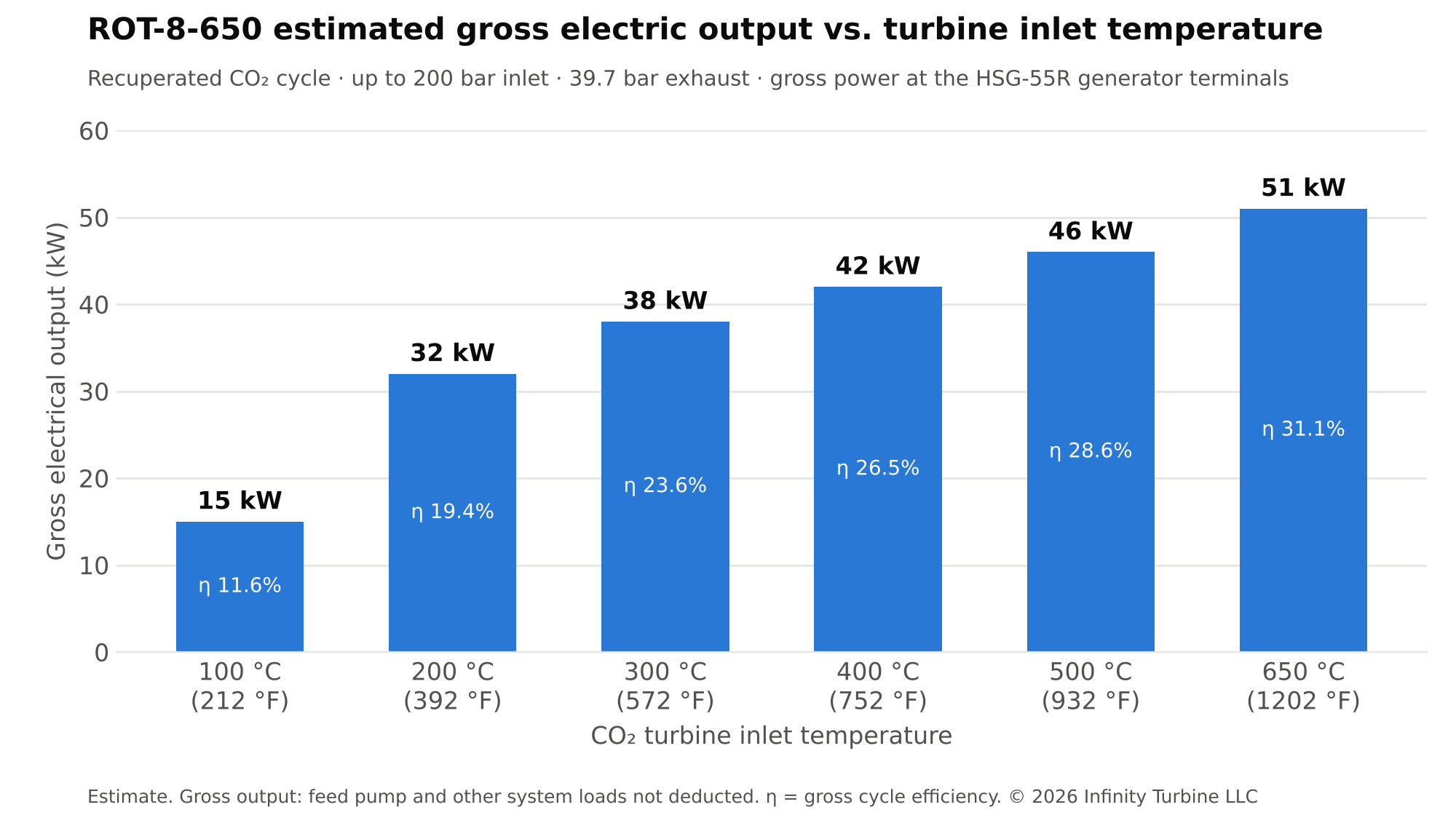
All outputs are gross: the power at the generator terminals. The same machine runs across a wide range of heat-source temperatures. Inlet pressure slides down at low temperature and nozzle-group valves trim the flow, while the inverter lets the shaft speed follow the best operating point.
| CO₂ turbine inlet | Gross output | Gross efficiency | Heat input | Heat input | Heat rate | Heat rate | Inlet pressure | CO₂ flow |
|---|---|---|---|---|---|---|---|---|
| kW | % | kWth | BTU/h | BTU/kWh | kJ/kWh | bar (psia) | kg/s | |
| 100 °C (212 °F) | 15 | 11.6 | 128 | 438,000 | 29,500 | 31,100 | 148 (2,150) | 0.54 |
| 200 °C (392 °F) | 32 | 19.4 | 164 | 560,000 | 17,600 | 18,600 | 200 (2,900) | 0.56 |
| 300 °C (572 °F) | 38 | 23.6 | 160 | 546,000 | 14,400 | 15,200 | 200 (2,900) | 0.48 |
| 400 °C (752 °F) | 42 | 26.5 | 160 | 545,000 | 12,900 | 13,600 | 200 (2,900) | 0.44 |
| 500 °C (932 °F) | 46 | 28.6 | 161 | 551,000 | 11,900 | 12,600 | 200 (2,900) | 0.40 |
| 650 °C (1,202 °F) | 51 | 31.1 | 165 | 564,000 | 11,000 | 11,600 | 200 (2,900) | 0.37 |
Gross output is the 3-phase power at the generator terminals. The CO₂ feed pump, power-electronics losses and other system loads are not deducted. Heat rate = heat into the CO₂ ÷ gross output. Plan on roughly 130–165 kWth (440,000–560,000 BTU/h, 460–600 MJ/h) of usable heat per turbine, at a source temperature about 50 °C (90 °F) above the turbine inlet temperature you want. On a wood-fired boiler at 80 % efficiency, the 650 °C heat rate on fuel is about 13,700 BTU/kWh (14,500 kJ/kWh) gross.
| CO₂ turbine inlet | Min. source temp. | Source cooled to ≈ | Flue / exhaust gas flow | or pressurized hot water | Wood fuel (80 % boiler) |
|---|---|---|---|---|---|
| 100 °C | 150 °C (300 °F) | 45 °C (113 °F) | — | 18 L/min (4.6 gpm) | 38 kg/h (84 lb/h) |
| 200 °C | 250 °C (480 °F) | 80 °C (176 °F) | — | 14 L/min (3.7 gpm) | 49 kg/h (108 lb/h) |
| 300 °C | 350 °C (660 °F) | 120 °C (248 °F) | 2,200 kg/h | — | 48 kg/h (106 lb/h) |
| 400 °C | 450 °C (840 °F) | 160 °C (320 °F) | 1,800 kg/h | — | 48 kg/h (106 lb/h) |
| 500 °C | 550 °C (1,020 °F) | 215 °C (419 °F) | 1,500 kg/h | — | 48 kg/h (106 lb/h) |
| 650 °C | 700 °C (1,290 °F) | 315 °C (599 °F) | 1,400 kg/h | — | 49 kg/h (108 lb/h) |
Gas flow assumes flue or engine exhaust gas (cp ≈ 1.12 kJ/kg·K). Wood fuel assumes air-dried wood at about 4.2 kWh/kg (≈15 % moisture). At 650 °C the CO₂ returns from the recuperator at about 285 °C, so the heat source only has to cover the top of the temperature range.
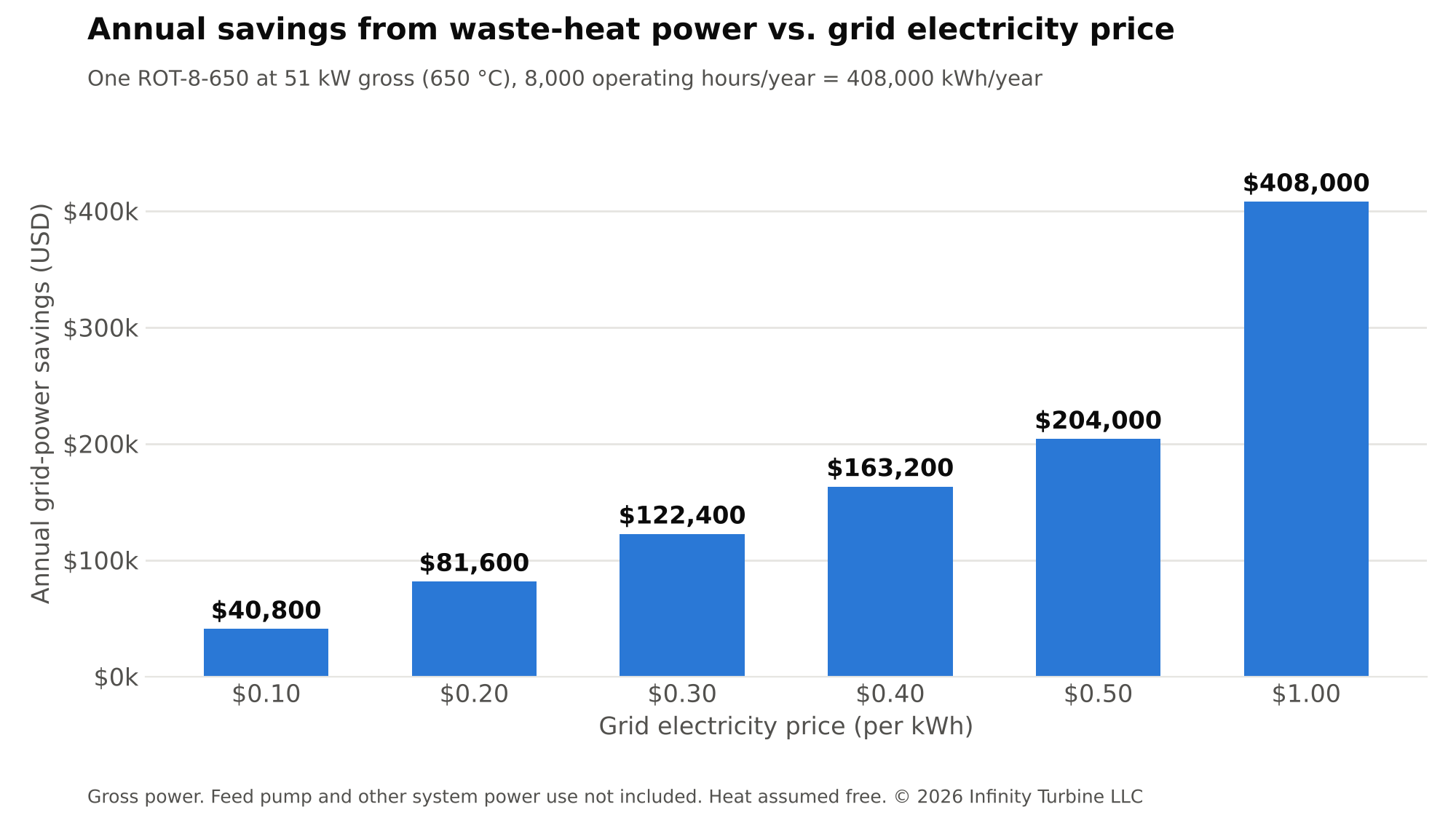
When the heat is already being thrown away, every kilowatt-hour the ROT-8-650 makes is one you don't buy from the grid. At 51 kW gross and 8,000 hours a year, one unit makes about 408,000 kWh a year.
| Turbine inlet / gross output | $0.10/kWh | $0.20/kWh | $0.30/kWh | $0.40/kWh | $0.50/kWh | $1.00/kWh |
|---|---|---|---|---|---|---|
| 100 °C · 15 kW | $12,000 | $24,000 | $36,000 | $48,000 | $60,000 | $120,000 |
| 200 °C · 32 kW | $25,600 | $51,200 | $76,800 | $102,400 | $128,000 | $256,000 |
| 300 °C · 38 kW | $30,400 | $60,800 | $91,200 | $121,600 | $152,000 | $304,000 |
| 400 °C · 42 kW | $33,600 | $67,200 | $100,800 | $134,400 | $168,000 | $336,000 |
| 500 °C · 46 kW | $36,800 | $73,600 | $110,400 | $147,200 | $184,000 | $368,000 |
| 650 °C · 51 kW | $40,800 | $81,600 | $122,400 | $163,200 | $204,000 | $408,000 |
Savings are based on gross power at the generator terminals. The feed pump and any other system power use are not included, and would reduce the savings. $0.40–$1.00/kWh is typical of diesel-generated power at remote sites, islands, mines and off-grid camps, where fuel delivery is part of the cost. Savings assume the heat is waste or free and exclude maintenance, financing and incentives. The balance of system (heat exchangers, CO₂ heater, recuperator, condenser, feed pump, piping, controls and power electronics) costs more than the turbine-generator, so base payback on the full installed cost.
The best sites have a steady, hot heat stream of roughly 110–170 kWth that runs most of the year. Higher temperature means more power from the same machine, so sources at 400 °C and above get the most out of it.
| Heat source | Typical temperature | Expected gross output | Fit | Why it works |
|---|---|---|---|---|
| Reciprocating engine exhaust (gensets, CHP, landfill and biogas engines) | 400–550 °C | 42–48 kW | Best | Hot, clean exhaust that runs around the clock; adds power without burning more fuel |
| Small gas turbine and microturbine exhaust | 450–600 °C | 44–50 kW | Best | High exhaust temperature and steady flow; a bottoming cycle for existing units |
| Kilns, furnaces, ovens (ceramics, glass, metals, heat treat) | 300–700 °C flue gas | 38–51 kW | Best | Large, continuous flue losses; a compact heater fits in the flue duct |
| Incinerators, thermal oxidizers, flares | 500–900 °C | 46–51 kW | Best | Very hot gas that is usually vented; power for the site from heat already being made |
| Solid oxide fuel cell exhaust | 600–800 °C | 50–51 kW | Best | High-grade exhaust raises total system efficiency |
| Biomass gasifiers and pyrolysis units | 500–800 °C | 46–51 kW | Strong | Syngas or char combustion heat on sites with free feedstock |
| Industrial process heat, dryers, thermal oil systems | 200–350 °C | 32–40 kW | Strong | Uses heat already circulated on site |
| Geothermal brine and hot wells | 100–200 °C | 15–32 kW | Good | Steady 24/7 heat; CO₂ needs no flammable or high-GWP working fluid |
| Data center and HVAC low-grade heat | 30–60 °C | — | Not suited | Too cold for this turbine; use a heat pump or a low-temperature CO₂ cycle |
The ROT-8-650 doesn't care where the heat comes from. That makes it a fit for remote sites that now run on diesel.
A CO₂ heater coil in the radiant section of a wood-fired furnace or boiler reaches 650 °C. Use firewood, chips, pellets or sawmill waste at camps, farms, sawmills and remote communities.
Parabolic troughs (300–400 °C) give 38–42 kW gross; towers and dishes (550–650 °C) give 48–51 kW. Plan on roughly 300–350 m² of collector aperture per turbine at 1,000 W/m² sun at 650 °C.
Brine at 150–250 °C runs the turbine at 100–200 °C inlet for 15–32 kW gross per unit, 24 hours a day. Several units can share one well field.
Charge a hot store from surplus solar or wind electricity, or from a burner, and run the turbine at night. Molten salt at about 565 °C gives roughly 48 kW gross.
Burners firing used oil, stranded associated gas or landfill gas supply 500–650 °C heat at oil fields, workshops and landfills.
Pair with batteries and solar PV. The turbine covers the base load from heat, so the diesel genset runs less, or only as a backup.
Modular blocks are bolted at individual flanges (16 × M10 on a 220 mm bolt circle), so each section can be machined, inspected and serviced on its own.
Tell us your heat source, its temperature and flow, and your electricity cost. We'll tell you what the ROT-8-650 can make on your site.
Performance basis. Figures are engineering estimates from a recuperated transcritical CO₂ cycle model (CoolProp properties), anchored to the ROT-8-650 design point: 200 bar / 650 °C inlet, 39.7 bar exhaust (≈5 °C condensing), 54 kW shaft, 22,600 rpm. Assumptions: turbine isentropic efficiency 58.7 % (from the design point), recuperator effectiveness 0.85, generator 95 %. All outputs are gross power at the generator terminals; the CO₂ feed pump, power-electronics losses and other system loads are not deducted. Inlet pressure is optimized up to 200 bar at each temperature. Warmer cooling water raises the condensing pressure and lowers output. The same model is used on the ROT-8-650 vs. CO2T-800 comparison page. Actual output depends on site conditions and final testing.
| CONTACT Email: greg@infinityturbine.com | AMP |